Device and method for assisting the alignment of limbs

a technology for applied in the field of assisting the alignment of joints and limbs, can solve the problems of poor function of premature failure of the prosthetic device, the potential for bending of the alignment rod, and the parallax error in the alignment of x-rays, etc., to facilitate the documentation of a medical procedur

Inactive Publication Date: 2011-06-16
JOINT RES
View PDF0 Cites 18 Cited by
  • Summary
  • Abstract
  • Description
  • Claims
  • Application Information

AI Technical Summary

Benefits of technology

[0028]In another embodiment, the device may include a camera arranged to facilitate documentation of a medical procedure performed with the device.
[0029]As explained above, the device may be utilised to determine a para-sagited plane transcending the centre of rotation of the hip joint. In more detail, the device employs the normal movement of the hip joint and geometric triangulation by use of visible light projected on to the body in a non invasive manner. The device then enables the external visualization of that plane by the projection of visible light. This plane can then be used as a guide by the operator to assess the mechanical axis of the limb.

Problems solved by technology

Errors in attaining the correct alignment can lead to ligament imbalance and misalignment of the prosthetic components, leading to poor function of premature failure of the prosthetic device.
The disadvantages of such an approach are considerable and include exposure of the patient and staff to greater levels of radiation from X-ray apparatus, the potential for bending of alignment rods and parallax error in the X-ray alignment.
Also, the imaging process increases the operating time and increases the risk of infection.
This is highly inaccurate due to movement of the patient during surgery, skin creep, or accidental dislodgement of the marker.
Preoperative imaging of the limb and measurement of the relative angles of the femoral intramedullary canal relative to the mechanical axis has been used for alignment of the femoral component, but this is limited to the femur and does not provide full limb alignment due to variables such as ligament laxity about the knee joint.
Intramedullary rod alignment also has an associated increase in the risk of complications, such as fat embolism, cortical penetration and fracture.
The necessity of this attachment, increases operating time, associated surgical trauma and morbidity.
Infection, haematoma and fracture at the reference frame attachment sites are published complications of this technique.

Method used


Image

  • Device and method for assisting the alignment of limbs
  • Device and method for assisting the alignment of limbs
  • Device and method for assisting the alignment of limbs

Examples


Embodiment Construction

[0039]For descriptive purposes the human lower limb will be used as the exemplary application of the invention however this does not exclude application to other joints and limbs in humans or other species.

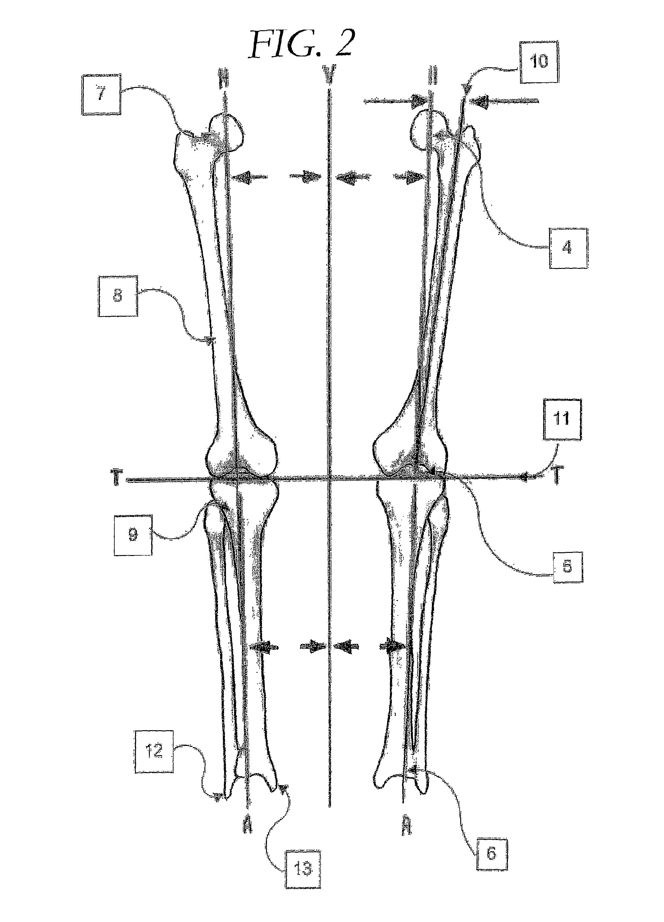
[0040]The embodiments described provide a method for determination of the centre of rotation of the joint, in this example, the centre of the head of the femur [17].

[0041]The femoral-acetabular articulation provides the origin of the weight bearing mechanical axis [4] of the lower limb.

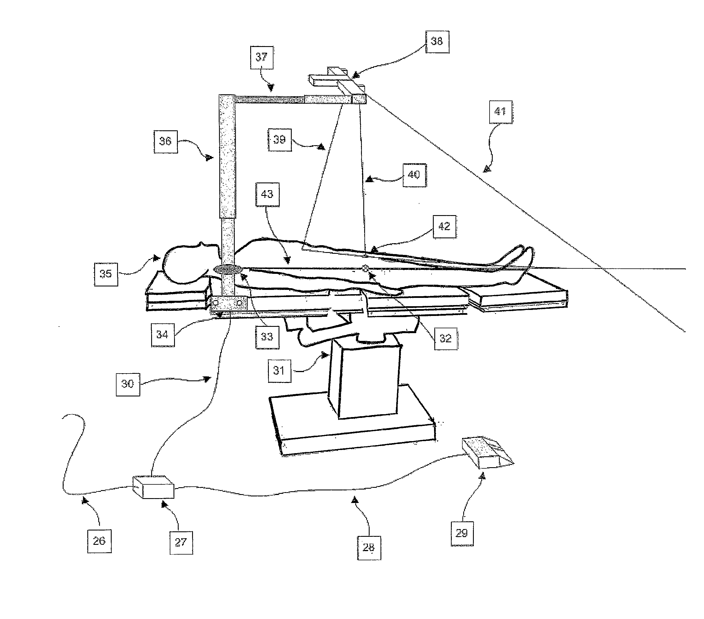
[0042]The apparatus employs geometric triangulation and the normal anatomical movement of the hip joint, to determine the centre of the hip joint rotation [17] or planar transections through the centre of rotation. A visible light projection device, such as a diode laser line generator, is used to project this alignment in one or more planes to enable the surgeon to make corrections to the alignment of the limb.

Geometric Basis of Function

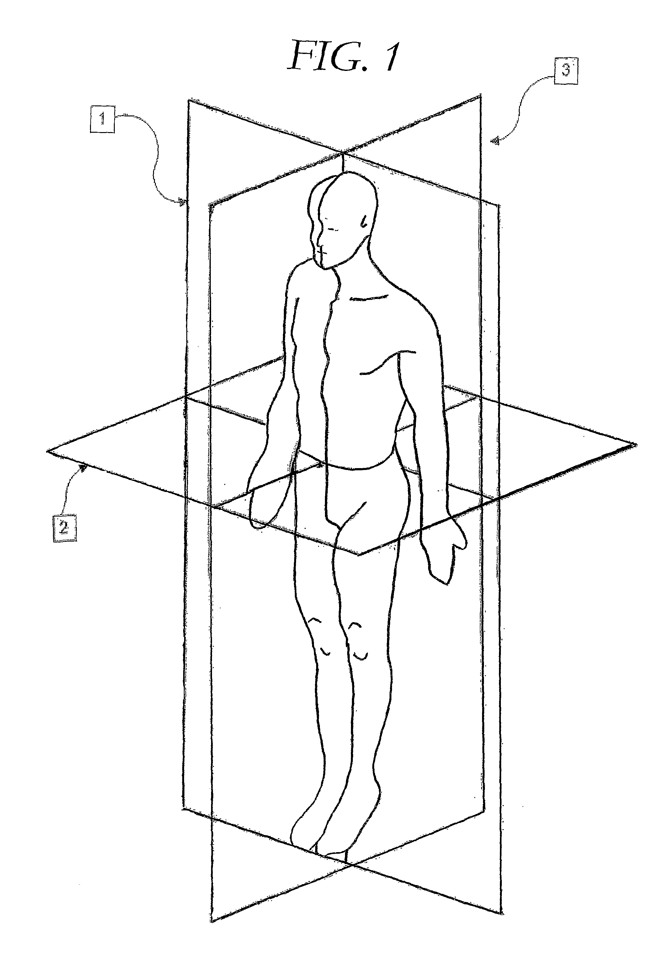
[0043]The hip, femoral-acetabular arthrosis (FIG. 3) functions...


PUM


Abstract

The present invention provides a device and method for determining the mechanical axis of a patient's limb. The device comprises a light source including a main light source arranged to project a beam of light onto the limb. The beam is adjusted to describe a plane of interest, to allow assessment of the mechanical axis of the limb.

Description

FIELD OF THE INVENTION[0001]This invention relates to devices for assisting in the alignment of joints and limbs of the human body. The invention provides particular, but not exclusive use as a tool for medical assessment, or in the case of surgical intervention, to assist in the restoration of anatomical or functional alignment of the limb.BACKGROUND TO THE INVENTION[0002]There has been an increasing interest in the replacement of damaged cartilage through the use of appropriate prosthetics and surgical intervention.[0003]The general process for insertion of a prosthetic knee component involves the surgical resection of the damaged cartilage on the joint surfaces in the knee region together with an amount of underlying bone to provide a site for attachment of the prosthetic component. The amount of bone resection is determined by the thickness of the prosthesis and restore an appropriate amount of tension to the ligamentous structures surrounding the joint to ensure that the joint ...

Claims


Application Information

Patent Timeline
Patent Type & Authority Applications(United States)
IPC IPC(8): A61B17/56
CPCA61B5/0064A61B5/4528A61B5/107
Inventor SWITZER, ANTHONY LAWRENCE
Owner JOINT RES
Why Eureka
Try Eureka