Methods and Systems for Emission System Control

Active Publication Date: 2011-06-23
FORD GLOBAL TECH LLC
View PDF16 Cites 44 Cited by
  • Summary
  • Abstract
  • Description
  • Claims
  • Application Information

AI Technical Summary

Benefits of technology

[0004]By positioning the filter upstream of the turbine, and the catalyst downstream of the turbine, the temperature of the SCR catalyst may be maintained even while the filter is being regenerated. By adjusting a turbine wastegate responsive to filter operation, the temperature of the SCR catalyst may be controlled. Thus, when the filter is storing particulates, flow through the wastegate may be increased to keep the catalyst temperature in th

Problems solved by technology

In SCR systems, variations in temperature may cause potential issues with both the conversion efficiency of the catalyst as well as the amount of reductant stored on the catalyst.
For example, as the temperature of the catalyst increases beyond a threshold, r

Method used


Image

  • Methods and Systems for Emission System Control
  • Methods and Systems for Emission System Control
  • Methods and Systems for Emission System Control

Examples


Embodiment Construction

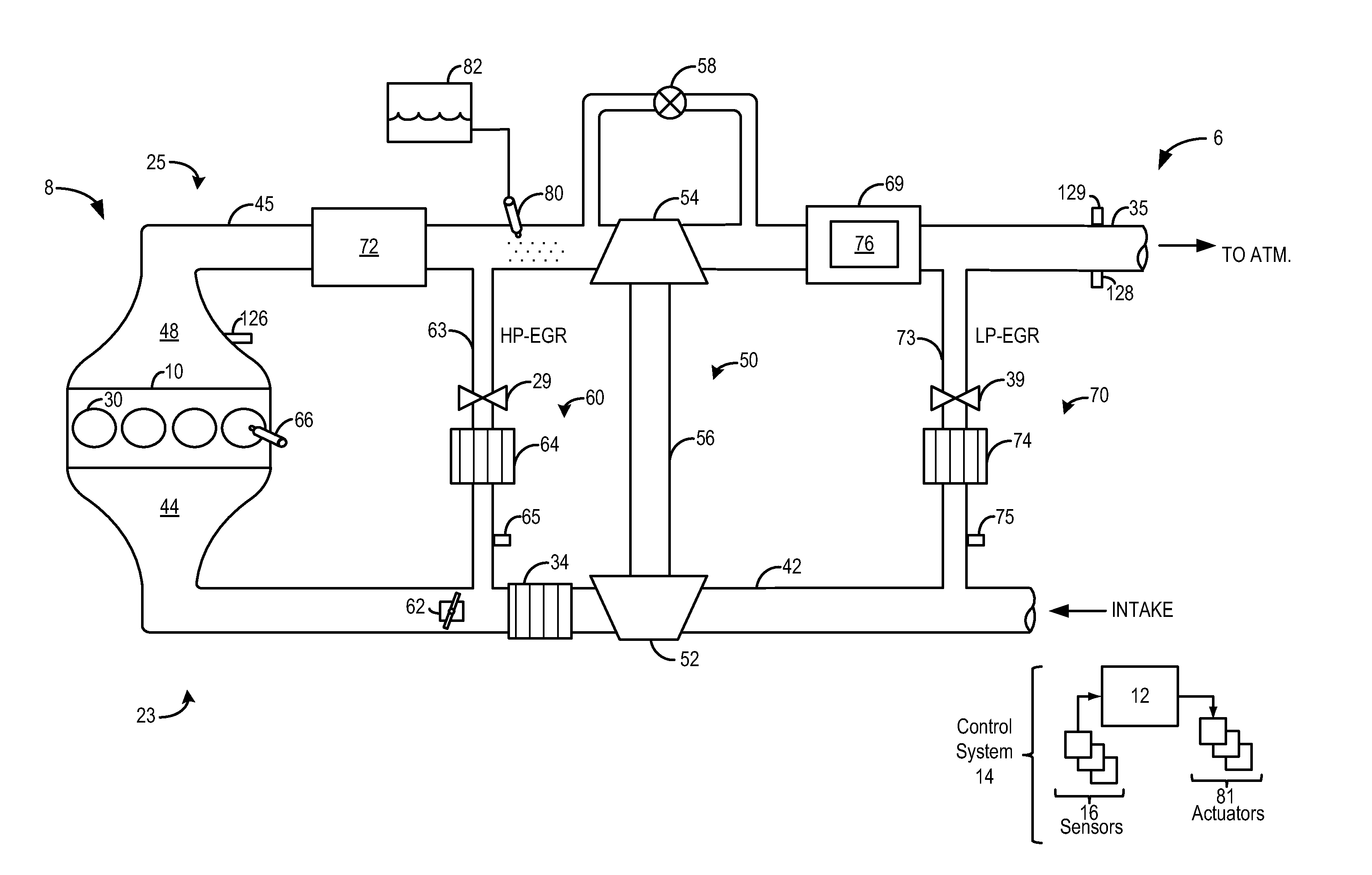
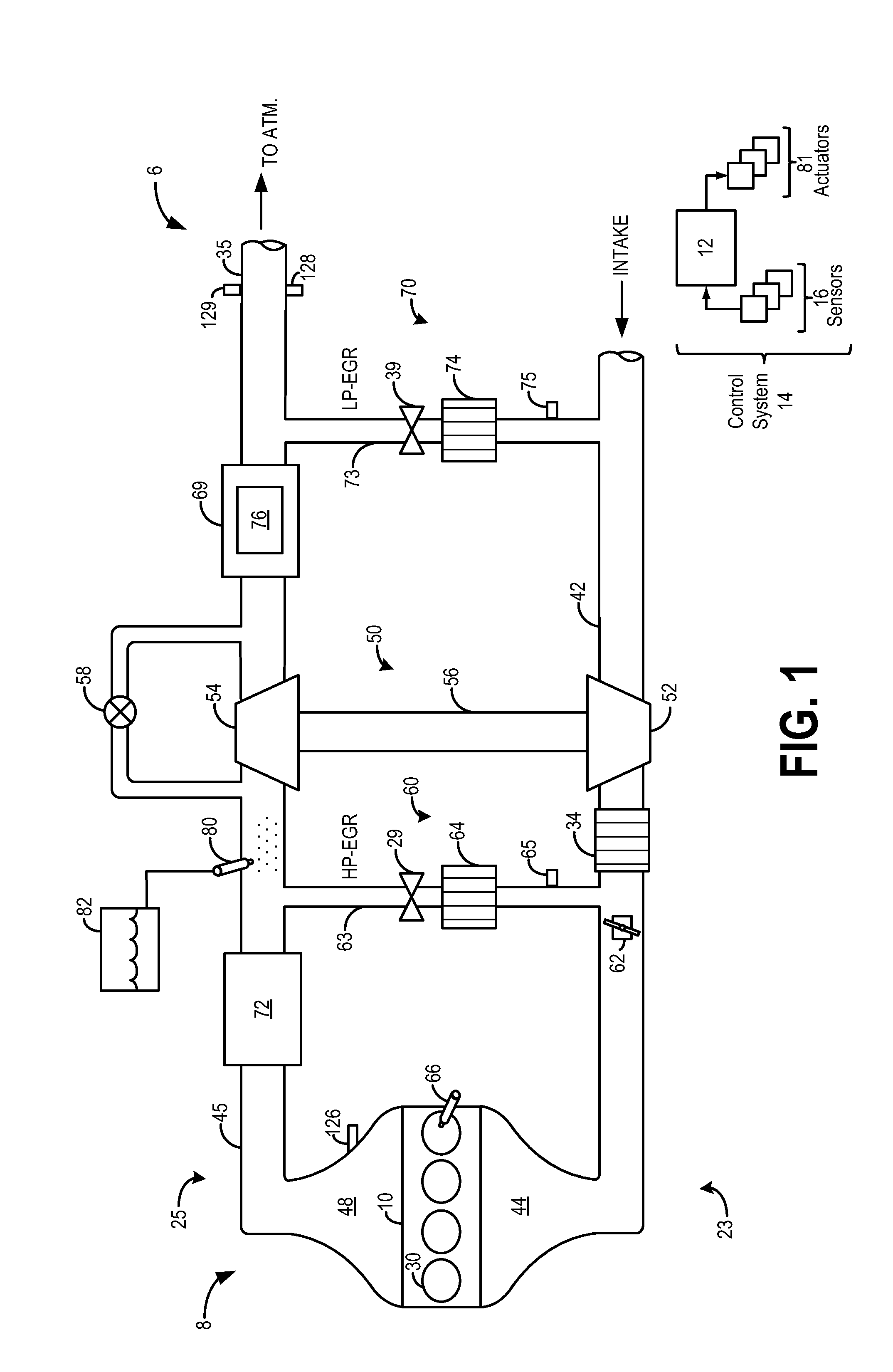
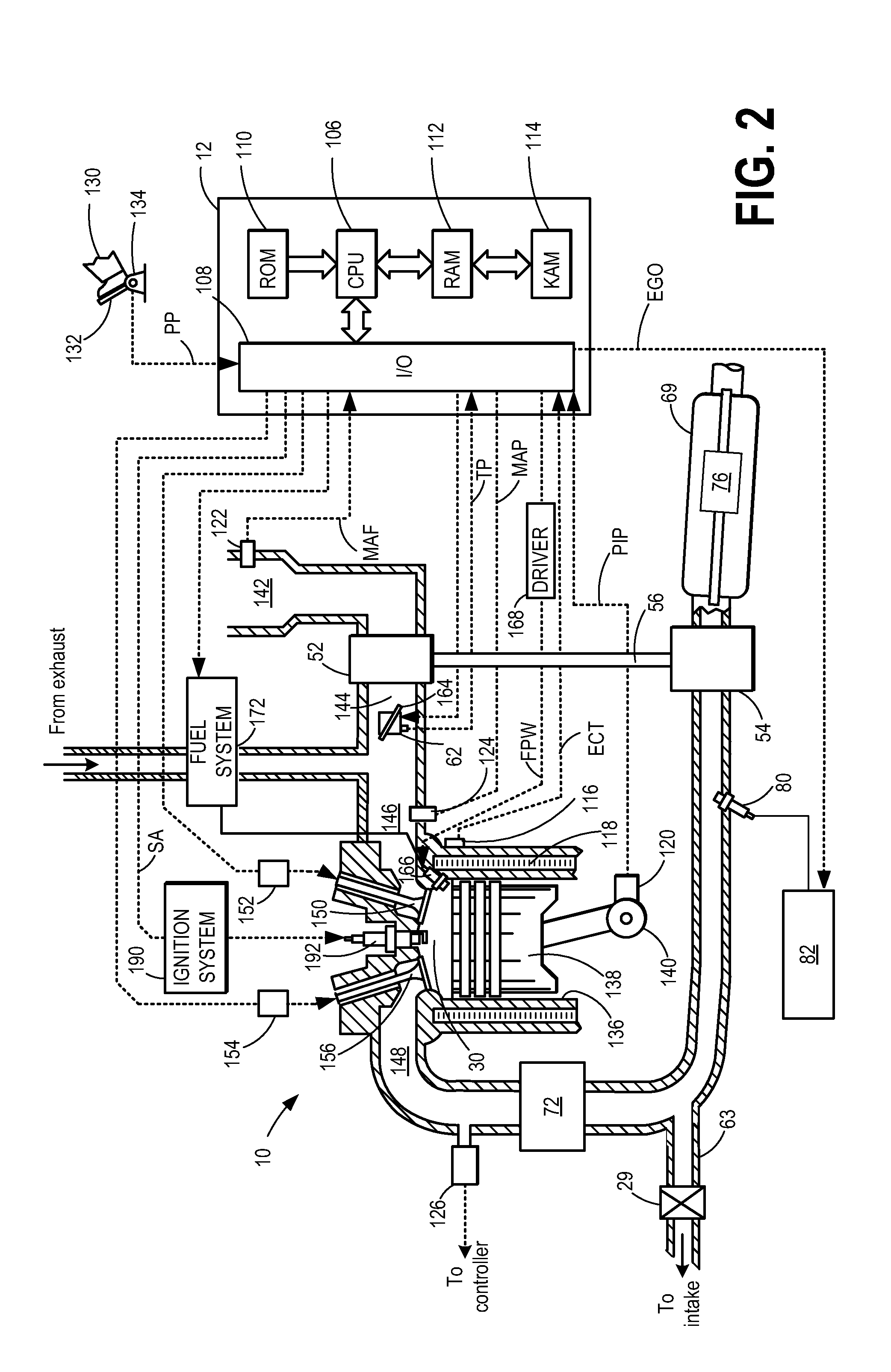
[0014]The following description relates to systems and methods for operating an emission control system associated with a turbocharged internal combustion engine. As shown in FIGS. 1-2, the emission control system includes a catalyst, such as an SCR catalyst, downstream of the turbocharger turbine, and a particulate filter, such as a diesel particulate filter (DPF), upstream of the turbine. A controller may be configured to perform a control routine, such as the routine of FIGS. 3A-B to coordinate the operation of the various emission control devices with each other, and with other engine operations such as exhaust gas recirculation and boosting.

[0015]The emission control system also includes a reductant injector upstream of the turbine. By injecting reductant upstream of the turbine and mixing the injected reductant with exhaust gas via the turbine, the vaporization of the reductant may be improved. At the same time, by positioning the catalyst downstream of the turbine, the well-m...


PUM


Abstract

Methods and systems are provided for operating an engine including an SCR catalyst downstream of an exhaust turbine and a particulate filter upstream of the turbine. In one example, the method comprises, adjusting a turbine wastegate to adjust a catalyst temperature to a desired catalyst temperature.

Description

FIELD[0001]The present application relates to methods and systems for emission control of a vehicle with a selective catalytic reduction (SCR) catalyst and a particulate filter.BACKGROUND AND SUMMARY[0002]Vehicle emission control systems may include selective catalytic reduction (SCR) systems to reduce NOx emissions. SCR systems involve injection of a reductant upstream of an SCR catalyst. The reductant, or reductant products, then reacts with exhaust NOx species to create byproducts such as nitrogen and water. In SCR systems, variations in temperature may cause potential issues with both the conversion efficiency of the catalyst as well as the amount of reductant stored on the catalyst. For example, as the temperature of the catalyst increases beyond a threshold, reductant may be desorbed from the SCR catalyst resulting in ammonia slip. Emission control systems may also include particulate filters for removing particulates from exhaust gas. During filter regeneration, heated exhaus...

Claims


Application Information

Patent Timeline
IPC IPC(8): F02D23/00F01N9/00F01N3/10F01N3/023F01N3/035F02D43/00F02B33/44
CPCF01N3/021Y02T10/24F01N9/00F01N2610/00F02D23/00F02D41/0007F02D41/024F02D41/029F02D41/1446F02D41/405F02D2200/0802F02M25/0707F02M25/0709Y02T10/144Y02T10/26Y02T10/47F01N3/2066F02M26/05F02M26/06Y02T10/12Y02T10/40
Inventor HEPBURN, JEFFREY SCOTTRUONA, WILLIAM CHARLESFULTON, BRIEN LLOYDSURNILLA, GOPICHANDRAKURTZ, ERIC MATTHEW
Owner FORD GLOBAL TECH LLC
Why Eureka
Try Eureka