Valve train of internal combustion engine

a technology of internal combustion engine and valve train, which is applied in the direction of valve drive, auxillary lubrication, shock absorption devices, etc., can solve the problems of valve motion abnormality, achieve high damping function, prevent the surging of the coil spring, and manufacture simple at low cost

Active Publication Date: 2011-06-23
HONDA MOTOR CO LTD
View PDF29 Cites 8 Cited by
  • Summary
  • Abstract
  • Description
  • Claims
  • Application Information

AI Technical Summary

Benefits of technology

[0005]An advantage of the present invention is to provide a valve train of an internal combustion engine equipped with a spring seat that can be manufactured simply at low cost and has a high damping function in order to prevent the surging of a coil spring.
[0006]One aspect of the instant invention relates to a valve train of an internal combustion engine including a valve reciprocated by a cam, and further including: a coil spring biasing the valve in a closing direction; and a spring seat provided at one end of the coil spring, the spring seat having a squeeze film effect of damping the axial motion of the coil spring.
[0007]In the above, the spring seat is designed to use the damping effect of the squeeze film damper; therefore, if the surging of the valve is reduced, the coil spring can be downsized. Thus, the engine can be downsized and the implanting depth of the valve stem guide can be ensured.
[0008]Another aspect of the invention is that in the valve train of an internal combustion engine, as described above, the spring seat has a structure provided with an oil slit radially intersecting and extending helically around a valve axis.
[0009]Accordingly, increasing the area of confronting surfaces of the oil slit is facilitated and it is not necessary to change the sectional shape of the coil spring. Since the helical portion is a singularly assembled part, the number of parts can be suppressed, the damping effect can be increased and the assembly performance can be enabled.
[0010]Another aspect of the invention is that in the valve train of an internal combustion engine, as described above, the helical oil slit of the spring seat has start and terminal points located axially offset inside, by a given distance, from a valve axial end face.

Problems solved by technology

A coil spring biasing each of the intake / exhaust valves of an internal combustion engine may cause surging, i.e., self-excited vibration during the high-speed rotation of the engine to result in the abnormal motion of the valve in some cases.

Method used


Image

  • Valve train of internal combustion engine
  • Valve train of internal combustion engine
  • Valve train of internal combustion engine

Examples


Embodiment Construction

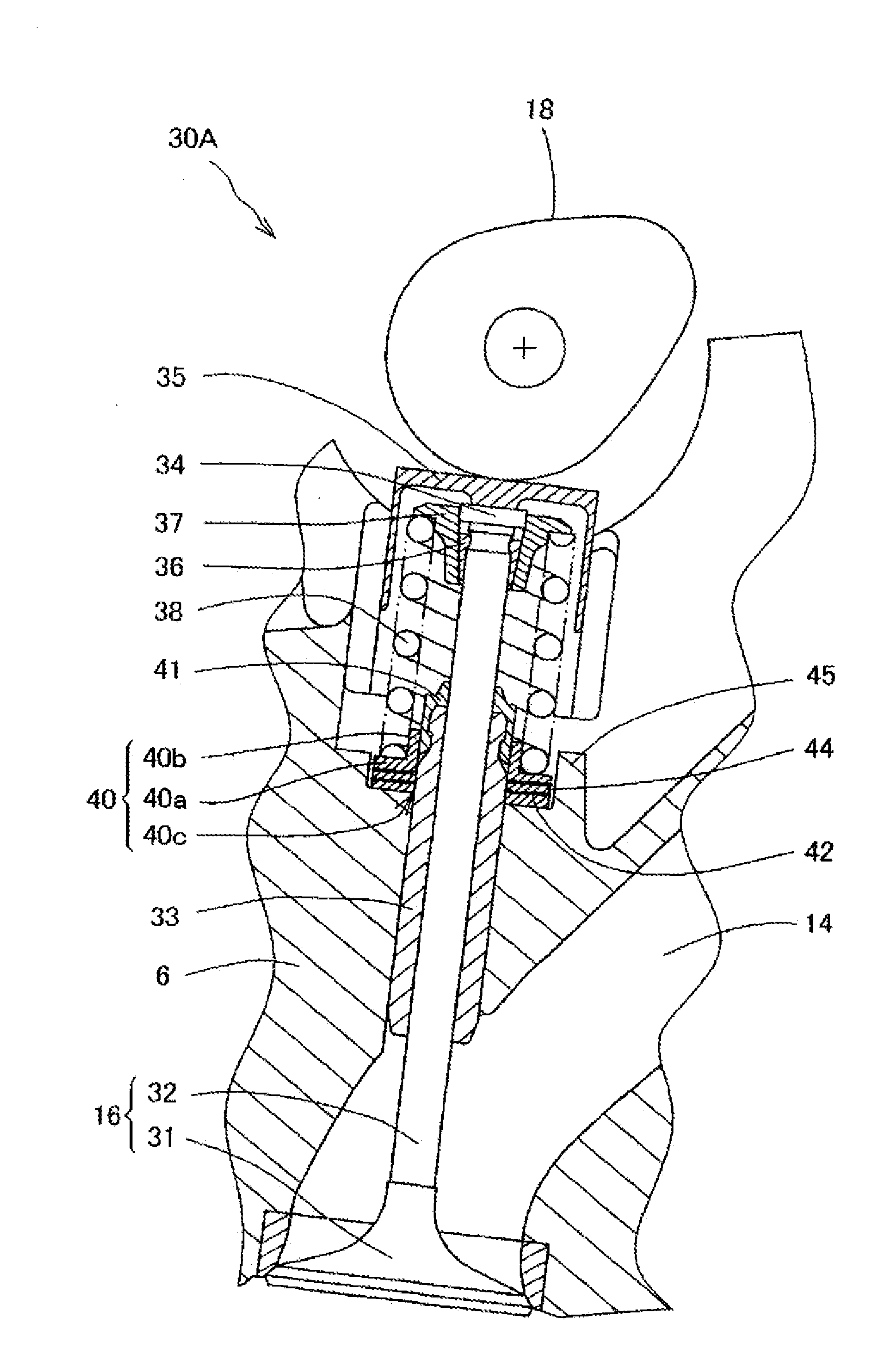
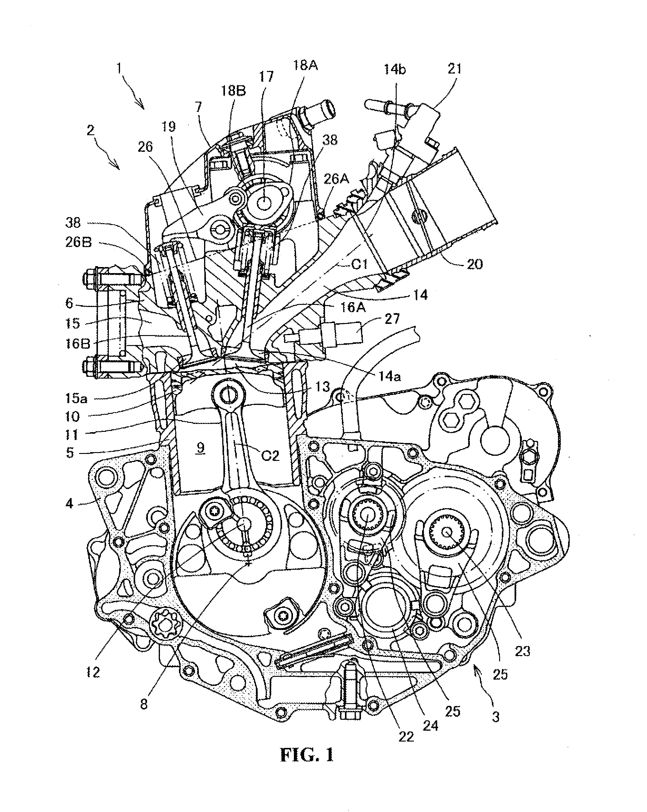
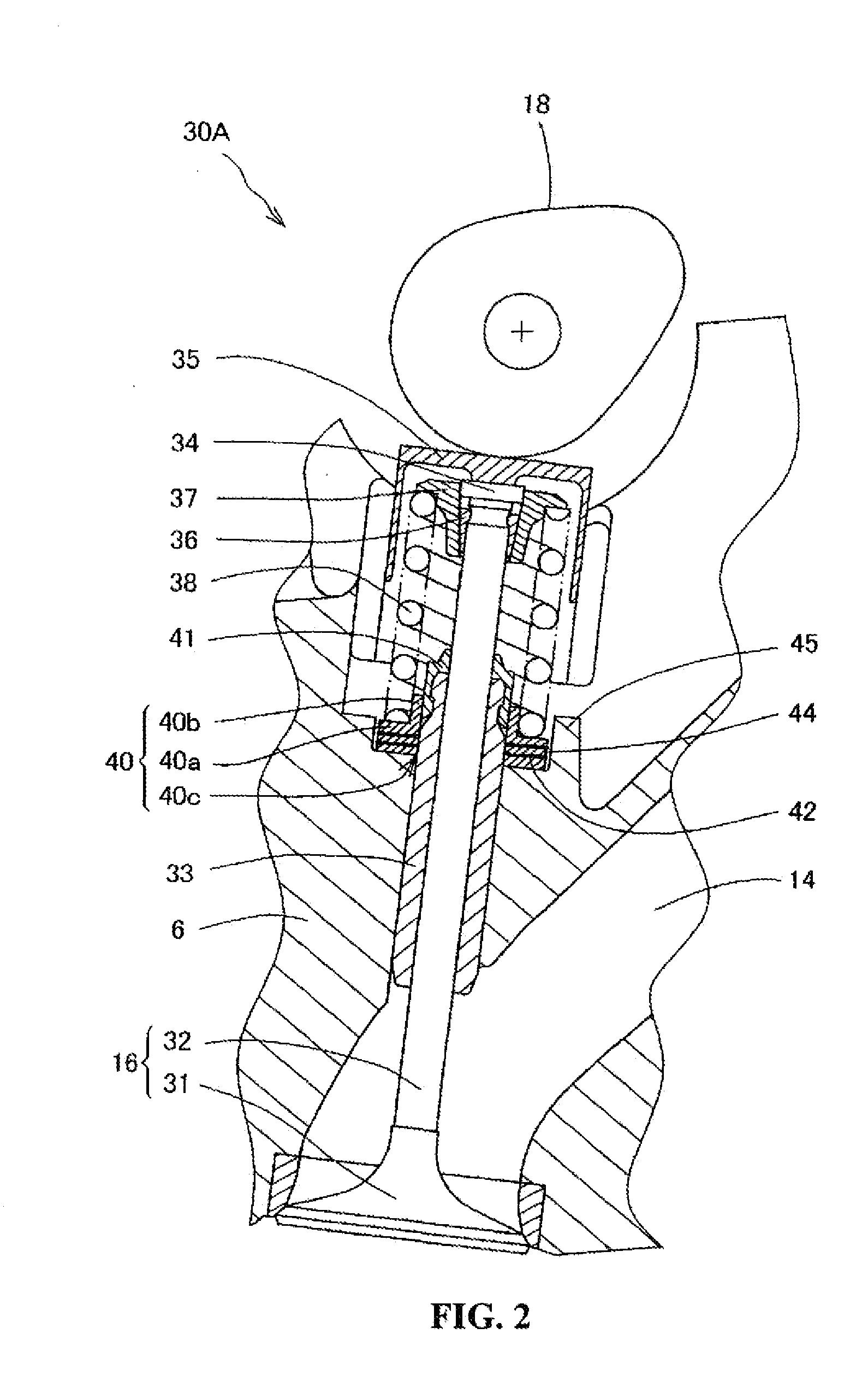
[0036]FIG. 1 is a lateral view of a motorcycle engine 1 to which a valve train of the present invention is applied. The engine is an integral engine 1 composed of an internal combustion engine 2 and a transmission 3. A shell of the engine 1 is composed of a crankcase 4, a cylinder block 5, a cylinder head 6 and a cylinder head cover 7. A crankshaft 8 is rotatably held in the crankcase 4. A cylinder bore 9 is formed in the cylinder block 5 so as to extend vertically cylindrically. In the cylinder bore 9 a piston 10 is provided vertically slidably. The piston 10 is connected to a crankpin 12 of the crankshaft 8 via a connecting rod 11. An intake port 14 and an exhaust port 15 formed in the cylinder head 6 communicate with a combustion chamber 13 formed by being surrounded by the cylinder bore 9, the cylinder head 6 and the piston 10. An intake valve 16A is provided at a combustion chamber side opening 14a of the intake port 14 and biased by a coil spring 38 in a direction of closing t...


PUM


Abstract

A valve train of an internal combustion engine equipped with a valve reciprocated by a cam is equipped with a spring seat manufactured in order to prevent the surging of a coil spring. A spring seat having a squeeze film effect of damping the axial motion of a coil spring is provided at one end of the coil spring in a closing direction. The spring seat is configured to be provided with an oil slit which radially intersects and extends helically around a valve axis.

Description

TECHNICAL FIELD[0001]The present invention relates to a valve train of an internal combustion engine having a structure for preventing a coil spring from causing surging.BACKGROUND OF THE INVENTION[0002]A coil spring biasing each of the intake / exhaust valves of an internal combustion engine may cause surging, i.e., self-excited vibration during the high-speed rotation of the engine to result in the abnormal motion of the valve in some cases. The following technology is disclosed as a means for preventing surging (Japanese Patent Laid-open No. Hei 8-177422 (FIGS. 1 and 2)). The coil spring is partially formed with a tight-winding portion. Mutual-contact portions between the spring members of the tight-winding portion are designed to contact each other through corresponding flat surfaces generally perpendicular to the axial direction of the coil spring.[0003]In this technology, at the normal rotation speed of the engine, the spring members of the tight-winding portion of the coil spri...

Claims


Application Information

Patent Timeline
Patent Type & Authority Applications(United States)
IPC IPC(8): F16F13/00
CPCF01L1/462F01L3/10F01L2101/00F01L2810/02F01L2810/03F16F2230/04F16F1/128F16F1/32F16F3/02F16F15/0237F01M9/10F01L2301/00
Inventor SAI, KOSHOKU
Owner HONDA MOTOR CO LTD
Why Eureka
Try Eureka