HF Ignition Device

Inactive Publication Date: 2011-06-23
BORGWARNER BERU SYST
View PDF25 Cites 21 Cited by
  • Summary
  • Abstract
  • Description
  • Claims
  • Application Information

AI Technical Summary

Benefits of technology

[0003]HF ignition devices causing ignition by means of a corona discharge are an alternative to conventional spark plugs which induce ignition using an arc discharge and are subject to considerable wear due to electrode burn-off. HF ignition devices have the potential to achieve a long service life, although this has not happened yet.
[0007]Surprisingly, the dielectric strength can be improved markedly by providing an electrically conductive coating on the section of the insulating body that encloses the housing body. In the case of an ignition device according to the invention, the electrically conductive coating of the insulating body, in combination with the center electrode, forms the capacitor, the dielectric of which is the insulating body. In contrast, in the case of the ignition device made known in EP 1 515 594 A2, the metallic housing body, in combination with the center electrode, forms the capacitor, thereby resulting in a less uniform electric field and, therefore, reduced dielectric strength.
[0008]The electrically conductive coating can be e.g. a metallic coating. The electrically conductive coating is preferably a ceramic coating, however. Ceramic coatings have the advantage of great hardness. A hard coating greatly reduces the risk of damage occurring when the insulating body is inserted into the housing body. This is an important advantage since damage to the coating creates a weak spot where field peaks can occur, which result in partial discharges.
[0010]The electrically conductive coating preferably has a thickness of less than 100 μm, particularly preferably less than 50 μm, in particular not more than 20 μm. Even very thin coatings are sufficient for improving the service life. Preferably, however, the coating has a thickness of at least 1 μm.
[0013]The electrically conductive coating preferably has a sheet resistance of less than 50Ω, particularly preferably of less than 20Ω, in particular not more than 10Ω. In general, the greater the conductivity of the coating is, the easier it is to prevent field peaks which can promote voltage overloads and partial discharges.
[0018]According to a further advantageous development of the invention, the end of the insulating body near the combustion chamber extends out of the housing body and covers the housing body at that point. In this manner, the insulating body can form a stop against which the housing body rests. Advantageously, this makes it easier to join the insulating body and the housing body e.g. by press fitting. In addition, a stop of this type can absorb the combustion chamber pressure that acts on the insulating body, thereby ensuring that seat of the insulating body in the housing body is not affected, in particular by pressure peaks that occur during engine operation.

Problems solved by technology

For frequencies of typically at least one MHz and voltages of a few kV, the dielectric strength during operation has proven to be problematic.
Voltage overloads and partial discharges often cause an HF ignition device to fail prematurely.
In contrast, in the case of the ignition device made known in EP 1 515 594 A2, the metallic housing body, in combination with the center electrode, forms the capacitor, thereby resulting in a less uniform electric field and, therefore, reduced dielectric strength.

Method used


Image

  • HF Ignition Device
  • HF Ignition Device
  • HF Ignition Device

Examples


Embodiment Construction

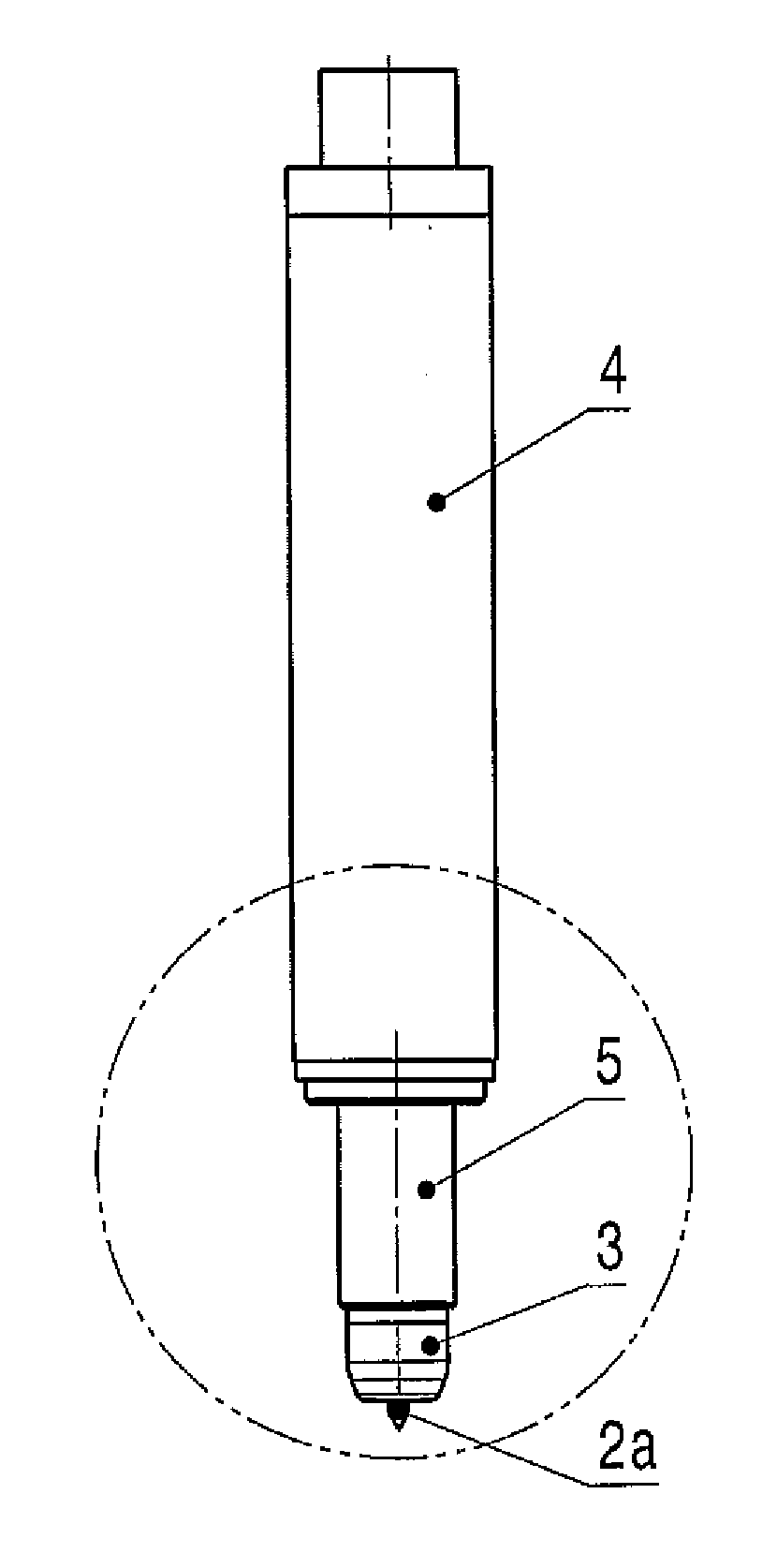
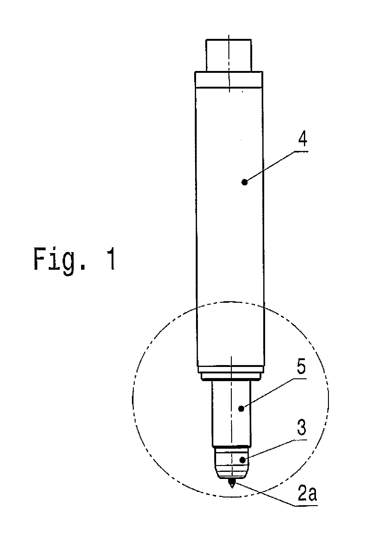
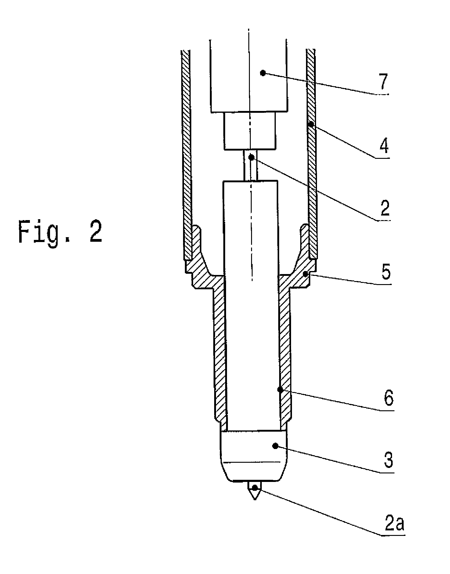
[0023]FIG. 1 shows a high-frequency ignition device for igniting a combustible gas mixture in an internal combustion engine. Image detail A encircled in FIG. 1 is shown in FIG. 2 in a sectional view.

[0024]The HF ignition device comprises a center electrode2 which terminates in an ignition tip 2a, a ceramic insulating body 3 through which center electrode 2 extends, and a housing 4 that carries, on one end thereof, a metallic housing body 5 that encloses at least one section of insulating body 3 and comprises an external thread 5a to be screwed into an internal combustion engine.

[0025]The section of insulating body 3 enclosed by housing body 5 comprises an electrically conductive coating 6 that is adjacent to housing body 5 and contacts it electrically. Electrically conductive coating 6 and center electrode 2 form a capacitor, the dielectric of which is the section of insulating body 3 covered by coating 6.

[0026]This capacitor is part of a circuit for the high-frequency excitation of...


PUM


Abstract

The invention relates to an HF ignition device for igniting a combustible gas mixture in an internal combustion engine, comprising a center electrode (2), an insulating body (3) through which center electrode (2) extends, a housing (4) that carries, on one end thereof, a metallic housing body (5) that encloses at least one section of insulating body (3), and comprising an external thread (5a) to be screwed into an internal combustion engine, and a circuit for the HF excitation of the center electrode (2). According to the invention, the section of the insulating body (3) that encloses the housing body (5) comprises an electrically conductive coating (6).

Description

[0001]The invention is directed to a high-frequency ignition device. An HF ignition device of this type is known from EP 1 515 594 A2.[0002]To ignite a combustible gas mixture in an engine, the center electrode of such an HF ignition device is excited using a suitable circuit e.g. an HF oscillating circuit. The center electrode then radiates high-frequency electromagnetic waves into the combustion chamber of the engine, thereby creating a plasma that induces ignition.[0003]HF ignition devices causing ignition by means of a corona discharge are an alternative to conventional spark plugs which induce ignition using an arc discharge and are subject to considerable wear due to electrode burn-off. HF ignition devices have the potential to achieve a long service life, although this has not happened yet.[0004]The problem addressed by the present invention is therefore that of demonstrating a way to improve the service life of an HF ignition device.SUMMARY OF THE INVENTION[0005]To excite th...

Claims


Application Information

Patent Timeline
IPC IPC(8): F02P3/01
CPCH01T13/36H01T23/00H01T13/50
Inventor ACHSTAETTER, TOMBRAEUCHLE, GERDDELESKY, HANSGIFFELS, THOMASHEILMANN, FELIZITAS
Owner BORGWARNER BERU SYST
Why Eureka
Try Eureka