Method for rinsing a fuel system of a gas turbine and associated fuel system

a fuel system and gas turbine technology, applied in the direction of machines/engines, cleaning using liquids, lighting and heating apparatus, etc., can solve the problems of lines and burners, and achieve the effect of preventing leakage of fuel and avoiding expensiveness

Active Publication Date: 2011-06-23
SIEMENS ENERGY GLOBAL GMBH & CO KG
View PDF17 Cites 23 Cited by
  • Summary
  • Abstract
  • Description
  • Claims
  • Application Information

AI Technical Summary

Benefits of technology

[0007]It is an object of the invention to create a method for flushing a section of a fuel system of a burner of a gas turbine, and also an associated fuel system, in which the aforementioned disadvantages are overcome and at the same time a simple and inexpensive manner of flushing is possible.
[0009]According to the invention, a method for flushing a section of a fuel system of a burner of a gas turbine is created with the following steps: providing a feed line for feeding fuel from a fuel source to the burner, providing a feed point which is close to the burner and a feed point which is remote from the burner in the feed line in each case for feeding medium into the feed line, feeding medium via the feed point which is close to the burner, and discharging, via the burner, the fuel which is in the feed line between the feed point which is close to the burner and the burner, and also feeding medium via the feed point which is remote from the burner, and discharging, via the feed point which is close to the burner, the fuel which is in the feed line between the feed point which is remote from the burner and the feed point which is close to the burner. The method of this type enables a simple, inexpensive and at the same time a particularly easily cleaning flushing of the feed line, particularly because in the case of the two flushing steps the fuel is delivered in the direction of the burner. The feed line is therefore flushed through in the same directions as the fuel also flows into it. This, so tests have shown, has the advantage that for example joints and connecting points in the feed line, which for reasons of construction are to be compulsorily provided, are cleaned better.
[0012]In the case of a third advantageous development of the method according to the invention, water is used as the medium. In the case of gas turbines water is already available in the NOx-water supply there, by means of which the water can be dosed into the burner during operation of the gas turbine in order to reduce the emission of nitrogen oxides.
[0017]In the case of a fourth advantageous development of the fuel system according to the invention, the said control elements are grouped together as a multifunction control element or multifunction valve, forming a constructional module. The multifunction control element of this type can be produced and also tested as a module. In addition, it is to be actuated within the fuel system with only one cable bundle, in all, therefore, especially inexpensively.
[0018]In the case of a fifth advantageous development of the fuel system according to the invention, a control element is provided in the feed line between the feed point which is close to the burner and the burner. This control element safely prevents leakage of fuel during the second method step.

Problems solved by technology

The coking would block lines and burners and therefore make them unusable.

Method used


Image

  • Method for rinsing a fuel system of a gas turbine and associated fuel system
  • Method for rinsing a fuel system of a gas turbine and associated fuel system

Examples


Embodiment Construction

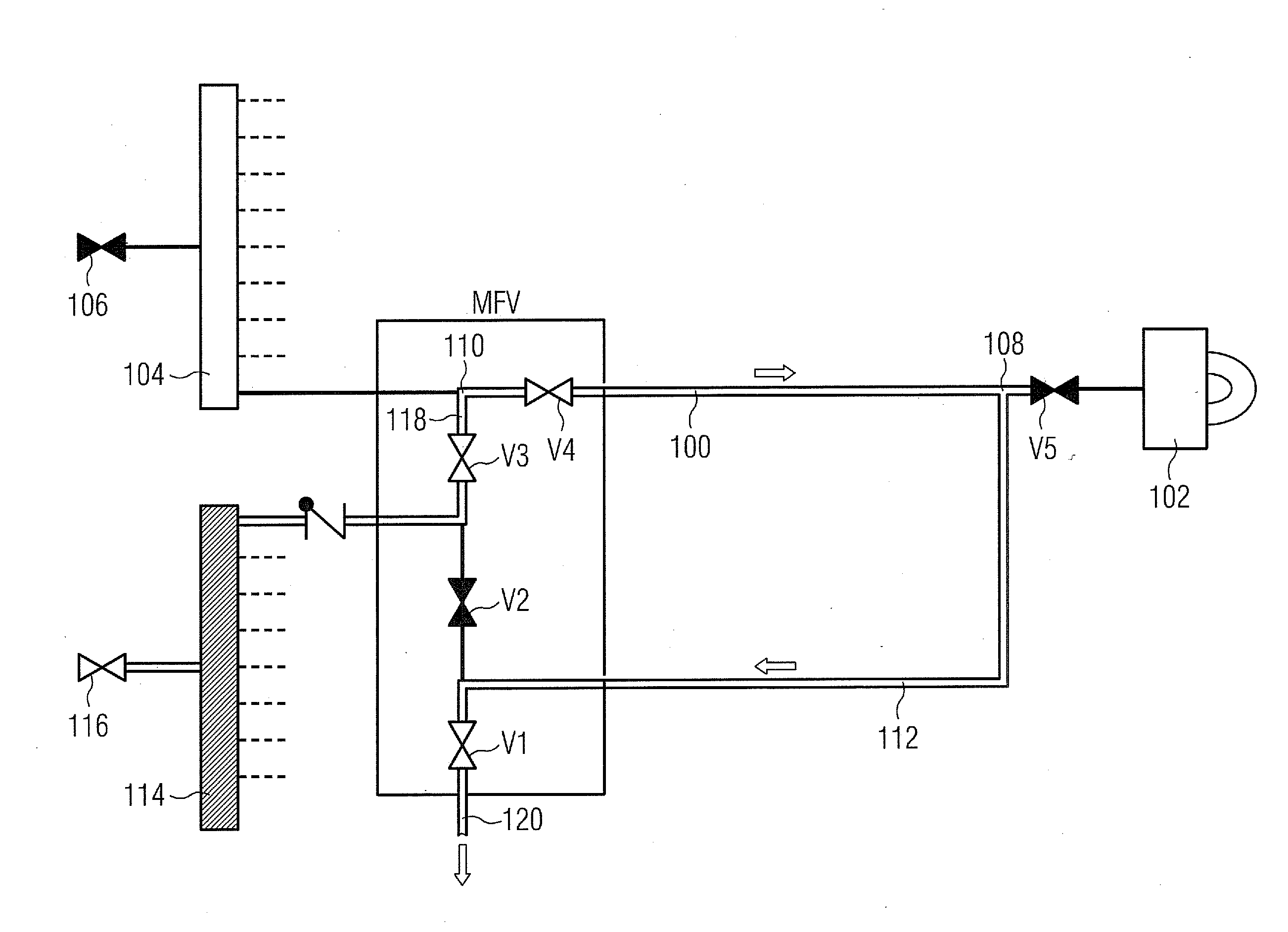
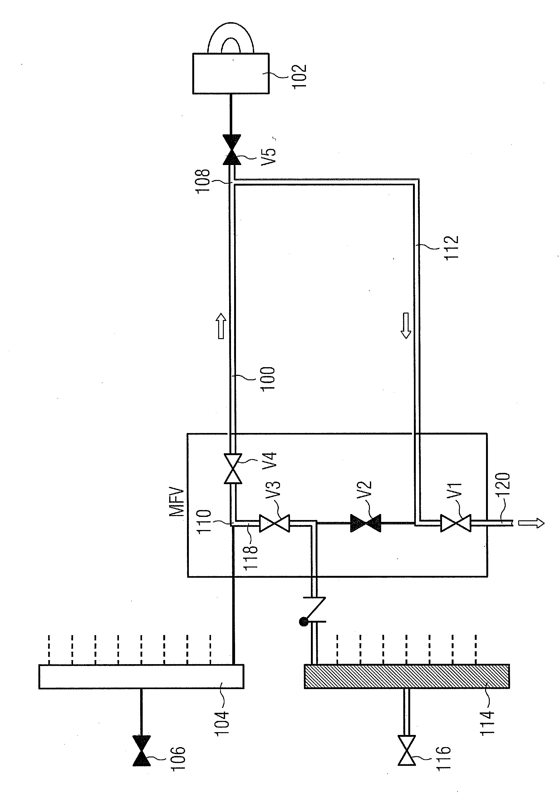
[0021]In FIG. 1, a fuel system according to the invention is shown, in which liquid fuel in the form of fuel oil from a (not shown) fuel source can be delivered through a valve 106, a fuel-oil flow-splitter 104, and a feed line 100 into one (of a plurality of) burner(s) 102. A feed point 108 which is close to the burner and a feed point 110 which is remote from the burner are formed in the feed line 100. A first feed line 112, through which water as flushing medium for the feed line 100 and the burner 102 can be made available through a valve V2, a water distributor 114 and a control valve 116 from an (not shown) NOx-water supply as a water source, leads to the feed point 108 which is close to the burner.

[0022]From the water-distributor 114, a second feed line 118, with a valve V3 arranged therein, leads to the second feed point 110. In addition, a valve V4 is arranged in the line section of the feed line 100 between the first and the second feed point 108 or 110. Finally, a drainag...


PUM


Abstract

A method for flushing a section of a fuel system of a burner of a gas turbine is provided. The method includes the steps of providing a feed line for feeding fuel from a fuel source to the burner, providing a first feed point close to the burner and a second feed point remote from the burner in the feed line in each case for feeding a medium into the feed line, feeding the medium via the first feed point, and discharging, via the burner, the fuel which is in the feed line between the first feed point and the burner, and also feeding the medium via the second feed point, and discharging, via the first feed point, the fuel which is in the feed line between the second feed point and the first feed point.

Description

CROSS REFERENCE TO RELATED APPLICATIONS[0001]This application is the US National Stage of International Application No. PCT / EP2009 / 055266, filed Apr. 30, 2009 and claims the benefit thereof. The International Application claims the benefits of German application No. 10 2008 027 409.7 DE filed Jun. 9, 2008. All of the applications are incorporated by reference herein in their entirety.FIELD OF INVENTION[0002]The invention refers to a method for flushing a section of a fuel system of a burner of a gas turbine with the steps: providing a feed line for feeding fuel from a fuel source to the burner and discharging or flushing out the fuel which is in the feed line. In addition, the invention refers to a fuel system of a burner of a gas turbine with a feed line for feeding fuel from a fuel source to the burner, and a feed point for feeding medium into the feed line.BACKGROUND OF INVENTION[0003]In the case of gas turbines with fuel oil operation, the fuel oil or the liquid fuel after opera...

Claims


Application Information

Patent Timeline
Patent Type & Authority Applications(United States)
IPC IPC(8): B08B9/02
CPCF01D25/002F02C7/222F02C7/232F05D2260/607F23K2301/203F23N2027/04F23K5/18F23N2227/04F23K2300/203Y10T137/0424
Inventor BASSMANN, CARSTENERTLE, VOLKERNIENHAUS, MICHAELRAUH, HORST UWERAZOWSKI, DAMIANSCHEUER, UWEWAGNER, ULRICH
Owner SIEMENS ENERGY GLOBAL GMBH & CO KG
Why Eureka
Try Eureka