
Vehicular control device

Active Publication Date: 2011-06-23
TOYOTA JIDOSHA KK
View PDF13 Cites 20 Cited by
  • Summary
  • Abstract
  • Description
  • Claims
  • Application Information

AI Technical Summary

Benefits of technology

[0017]In the above-described configuration, the blower is prohibited from being actuated in a period from starting of the engine to completion of warm-up of the catalyst, even if heating is requested. When actuation of the blower is prohibited, air is prevented from flowing through the actuation of the blower and being subjected to heat exchange with the heat exchanging fluid at the heat exchanger on the circulation path. Accordingly, after the heat produced by the engine is supplied to the heat exchanging fluid, the heat is prevented from being sent into the passenger compartment by means of the aforementioned air. This rapidly raises the temperature of the engine and the temperature of the heat exchanging fluid, thus increasing exhaust temperature of the engine. The heat is thus efficiently supplied to the catalyst by means of exhaust gas from the engine. In other words, the heat generated by the engine is distributed preferentially to the catalyst, which is a component of the vehicle that must be heated when at a low temperature, aside from the passenger compartment. As a result, after starting of the engine is initiated, the catalyst bed temperature quickly rises to the activation level and the catalyst is completely warmed up. This prevents retardation in increase of the catalyst bed temperature to the activation level, or, in other words, retardation in completion of the warm-up of the catalyst, after initiation of starting of the engine. The engine is thus prevented from being retarded in improving the exhaust emission by the amount corresponding to such retardation.
[0055]In the above-described configuration, when the economy mode is selected by the occupant, actuation of the blower is permitted from a prohibited state only after the temperature of the heat exchanging fluid increases to a high value after initiation of engine starting, compared with when the normal mode is selected. In other words, after starting of the engine is initiated, the heat generated by the engine is distributed further preferentially to the heat exchanging fluid over the passenger compartment. This further rapidly raises the temperature of the heat exchanging fluid after the initiation of starting of the engine, thus further quickly completing warm-up of the engine.

Problems solved by technology

This rapidly raises the temperature of the engine and the temperature of the heat exchanging fluid, thus increasing exhaust temperature of the engine.

Method used


Image

  • Vehicular control device
  • Vehicular control device
  • Vehicular control device

Examples


first embodiment

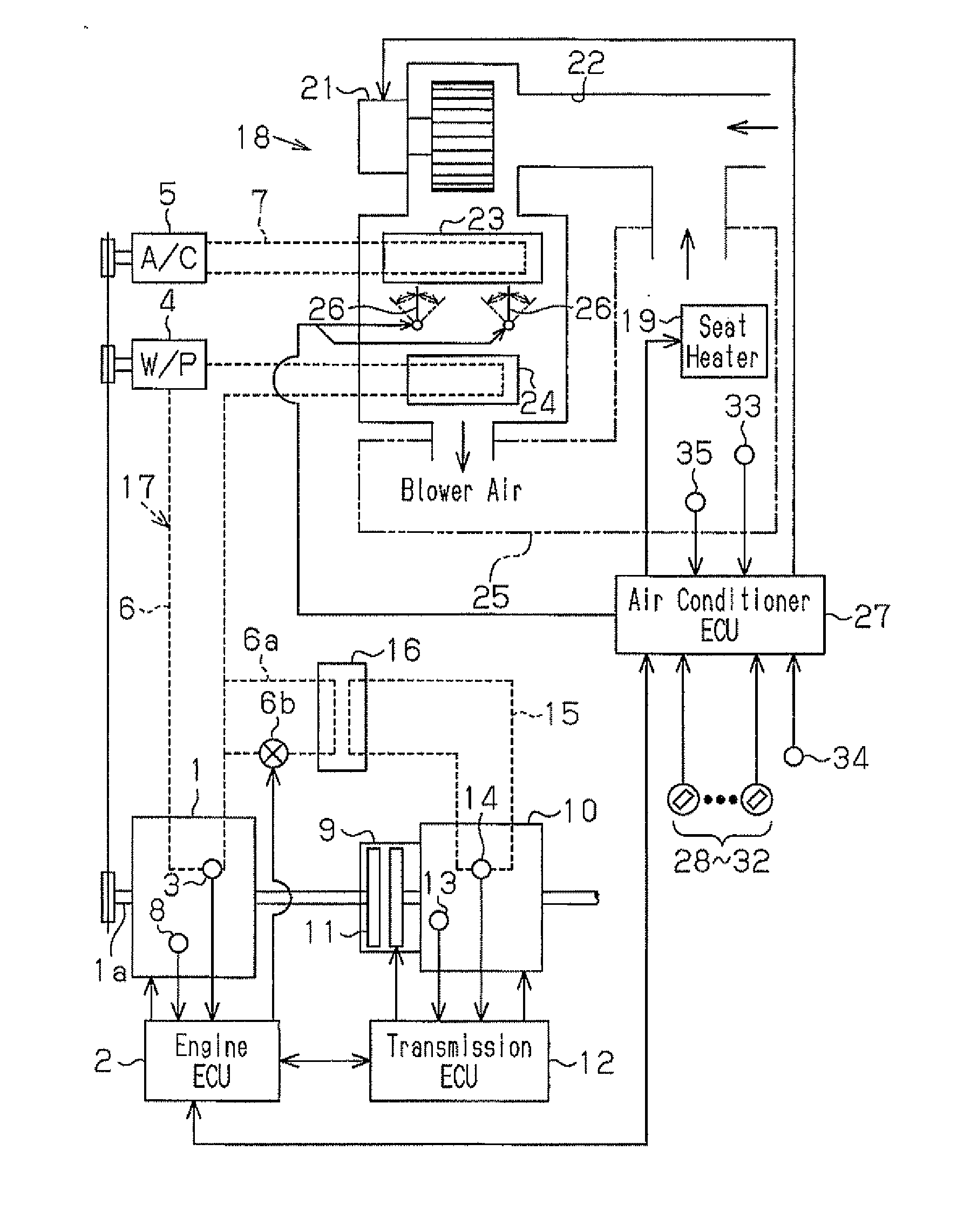
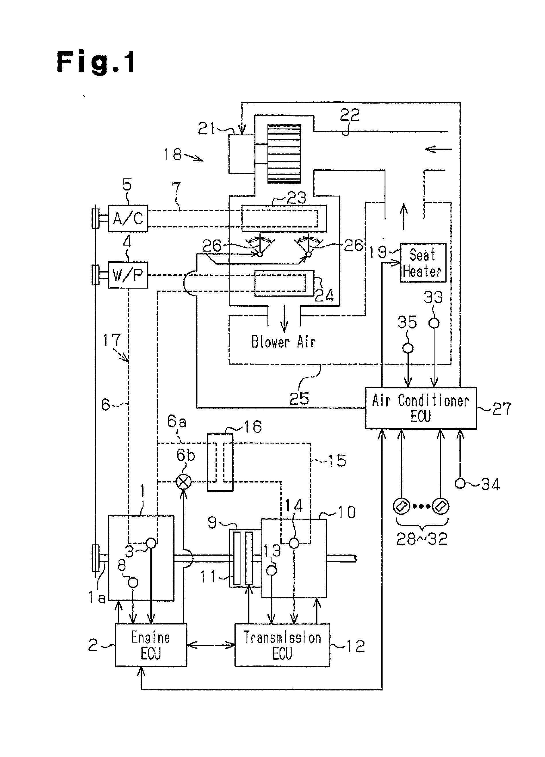
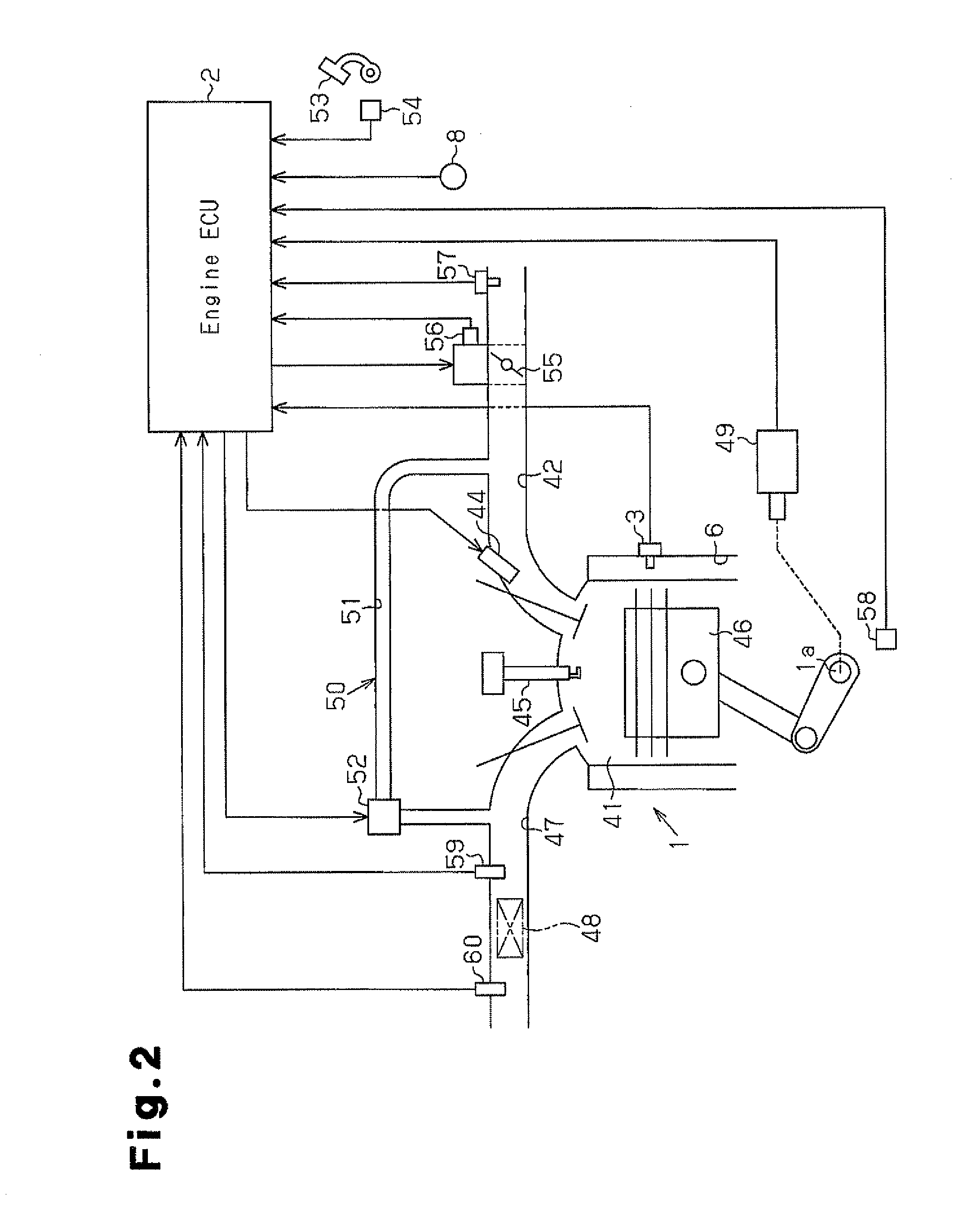
[0070]A first embodiment of the present invention, which is a control device for an automobile, will now be described with reference to FIGS. 1 to 6.

[0071]In an automobile, as represented in FIG. 1, a transmission 10 is connected to an output shaft 1a of an engine 1, which is mounted as a motor. The automobile runs as rotational force from the engine 1 (via the output shaft 1a) is transmitted to wheels through the transmission 10. The transmission 10 has a torque converter 9 and a lockup clutch 11. The torque converter 9 transmits the drive force from the engine 1 to a transmission mechanism, which is provided in the transmission 10, through oil. The lockup clutch 11 is capable of connecting the engine 1 and the transmission mechanism directly to each other. The lockup clutch 11 and the transmission mechanism of the transmission 10 are operated using hydraulic pressure produced by transmission oil, which is hydraulic fluid in the transmission 10.

[0072]The automobile also includes a ...

second embodiment

[0137]A second embodiment of the present invention will hereafter be described with reference to FIG. 7.

[0138]In the automobile in which thermal efficiency of the engine 1 is improved by reducing the size of the engine 1 or ensuring automatic stopping and restarting, transmission oil used by the transmission 10 may be considered as a component aside from the passenger compartment 25 that must be heated when at a low temperature.

[0139]The transmission 10 achieves such an operating state that the transmission 10 contributes to reduction in fuel consumption of the engine 1 when the temperature of the transmission oil increases to a value (which is, for example, a determination value H1) that is high to a certain extent compared with the normal value at the time when the engine 1 is held in a stopped state. Accordingly, to decrease the fuel consumed by the engine 1, the flow control valve 6b of the branch line 6a communicating with the circulation path 6 of the heat exchanging device 17...

third embodiment

[0151]A third embodiment of the present invention will hereafter be described with reference to FIG. 8.

[0152]In an automobile in which thermal efficiency of the engine 1 is enhanced by reducing the size of the engine 1 or performing automatic stopping and restarting, the lubricant oil used by the engine 1 may also be cited as a component aside from the passenger compartment 25 that must be heated when at a low temperature.

[0153]In the engine 1, the viscosity of the lubricant oil decreases when the temperature of the lubricant oil increases to a value (which is, for example, a determination value H2) that is high to a certain extent compared with the normal value at the time when the engine 1 is in a stopped state. This reduces the resistance of the lubricant oil to the rotation of the engine 1, thus allowing the engine 1 to operate efficiently. The engine 1 is thus allowed to operate in a state effective for decrease of the fuel consumption by the engine 1. Accordingly, to reduce th...


PUM


Abstract

During the time period from the start of an engine to the completion of a catalyst warming-up, the drive of a blower in an air-conditioning equipment is inhibited to suppress the heat-exchange of the air, which is caused to flow in an air duct by the drive of the blower, with cooling water in a heater core disposed in a circulating passage. Therefore, the heat generated in the engine is restrained from being fed to the inside of a compartment through that air after fed to the cooling water. As a result, the temperatures of the engine and the cooling water rise quickly, and the temperature of the exhaust of the engine rises so that the heat is efficiently fed to the catalyst through the exhaust. This means that the heat generated in the engine is preferentially fed through the exhaust to the catalyst that is the portion needing the feed of heat at a low temperature, other than the compartment in the automobile.

Description

TECHNICAL FIELD[0001]The present invention relates to a vehicular control device.BACKGROUND ART[0002]Conventionally, a vehicle such as an automobile includes a heat exchanging device for exchanging heat with an internal combustion engine, which is a motor, to cool the engine and an air conditioning device for heating the interior of the passenger compartment using the heat transmitted from the engine to the heat exchanging device.[0003]The heat exchanging device circulates heat exchanging fluid in a circulation path passing through the engine and thus causes heat exchange between the fluid and the engine. When heated to a high temperature, the engine is cooled through such heat exchange between the heat exchanging fluid and the engine. The air conditioning device has a blower driven to discharge warm air into the passenger compartment. When the blower is activated, the air is passed through a heat exchanger on the circulation path in the heat exchanging device. This causes heat exch...

Claims


Application Information

Patent Timeline
IPC IPC(8): B60H1/02F01N3/18F02M25/07
CPCY10T477/653F01N3/2006F02M25/07F01P2060/08F01P2037/02B60H1/00828B60H1/034B60H1/00764F01P7/08F02M26/00Y02A50/20
Inventor MORITA, MASAKIMIYAMOTO, YUKI
Owner TOYOTA JIDOSHA KK
Learn More