Device for fixing biomass-based solar heat and carbon dioxide gas, and house equipped with same fixing device

a solar heat and carbon dioxide gas and biomass-based technology, which is applied in the direction of mechanical energy handling, mechanical equipment, machines/engines, etc., can solve the problems of not significantly improving the productivity of agriculture and forestry, lack of stability, and control of conventional agricultural and forest technology based on mountain forest and farm field, etc., to achieve the effect of reducing environmental loads, and reducing the number of contaminated areas

Inactive Publication Date: 2011-06-23
PLUS KAKEN INNOVATE LABO
View PDF4 Cites 29 Cited by
  • Summary
  • Abstract
  • Description
  • Claims
  • Application Information

AI Technical Summary

Benefits of technology

The patent describes a device for fixing biomass-based solar heat and carbon dioxide gas. The device includes a porous body made of active carbon, foamed ceramics, and ion-exchange resin that is placed in a water reservoir tray. The porous body ionizes the water it comes in contact with, increasing the concentration of ions in the air and soil near the water surface. This results in the supply of ionized water, air, and nutrients to the biomass, promoting its growth. The device also includes a water level adjustment unit to control the amount of water supplied to the biomass. Additionally, the patent describes a house equipped with the fixing device, which allows for the efficient use of solar energy and the cultivation of plants. The house also includes a bio auxiliary equipment to operate the device effectively and a biomass concentrated incubator to supply electricity to the house while minimizing environmental impact. The device and the house equipped with it provide a convenient and efficient solution for generating energy and promoting plant growth.

Problems solved by technology

The patent text discusses the problem of traditional agricultural and forestry methods being controlled by natural environment and lacking stability, as well as the increasing demand for food and biofuels due to population and industrialization. To address this, modernization has led to the development of artificial cultivation environments using hydroponic cultivation and plastic greenhouses. However, these methods are not efficient in terms of productivity and carbon dioxide gas reduction. Additionally, the text highlights the issue of long-distance transportation of commodities causing energy loss and social problems. The technical problem of the patent text is to improve the production of biomass and reduce carbon dioxide gas emissions through the development of efficient and stable agricultural and forestry technology.

Method used


Image

  • Device for fixing biomass-based solar heat and carbon dioxide gas, and house equipped with same fixing device
  • Device for fixing biomass-based solar heat and carbon dioxide gas, and house equipped with same fixing device
  • Device for fixing biomass-based solar heat and carbon dioxide gas, and house equipped with same fixing device

Examples


second embodiment

[0094]Next, second embodiment of a device for fixing biomass-based solar heat and carbon dioxide gas is explained with reference to FIG. 6. Here, in the following explanation, identical symbols are added to the similar constitution as the above mentioned fixing device A, and the explanation is omitted. Further, in FIG. 6, for convenience of explanation, the water reservoir tray 4 is omitted.

[0095]FIG. 6 is an exploded explanatory view showing a box part 30 of a fixing device B according to a second embodiment. As also shown in FIG. 6, the fixing device B, as compared with the fixing device A, differs in structure in a point that the fixing device B includes a cylindrical external wall material 31.

[0096]To be more specific, on the surface of the external wall material 31, a plurality of air pores 32 as an air intake unit is bored and is configured to efficiently supply air to the soil held in the inside of the external wall material 31.

[0097]In the conventional agricultural technolog...

third embodiment

[0098]Next, a third embodiment of a device for fixing biomass-based solar heat and carbon dioxide gas is explained with reference to FIG. 7. FIG. 7 is an explanatory view of a fixing device C having an approximately rectangular shape on a plan view for using long root vegetables as biomass. The fixing device C differs in a structure in a point that a box part 30 is configured to have an approximately rectangular shape on a plan view as compared with the fixing device B in the above mentioned second embodiment which has an approximately circular shape on a plan view.

[0099]Further, the fixing device C is characterized in that a plurality of box parts 30 are arranged on one water reservoir tray 4.

[0100]Due to such a constitution, it is possible to give biomass planted in any one of the box parts 30 the same growing condition (water and ion concentration), thus enabling to grow most uniform possible biomass.

[0101]Further, an aeration passage 6 is formed of substance which sympathizes wi...

fourth embodiment

[0105]Next, a fourth embodiment of a device for fixing biomass-based solar heat and carbon dioxide gas is explained with reference to FIGS. 8 to 10. FIG. 8 is an oblique perspective view showing an appearance of a fixing device D according to the fourth embodiment, FIG. 9 is an exploded explanatory view showing a constitution of the fixing device D, and FIG. 10 is an explanatory view on a cross-sectional view of the fixing device D.

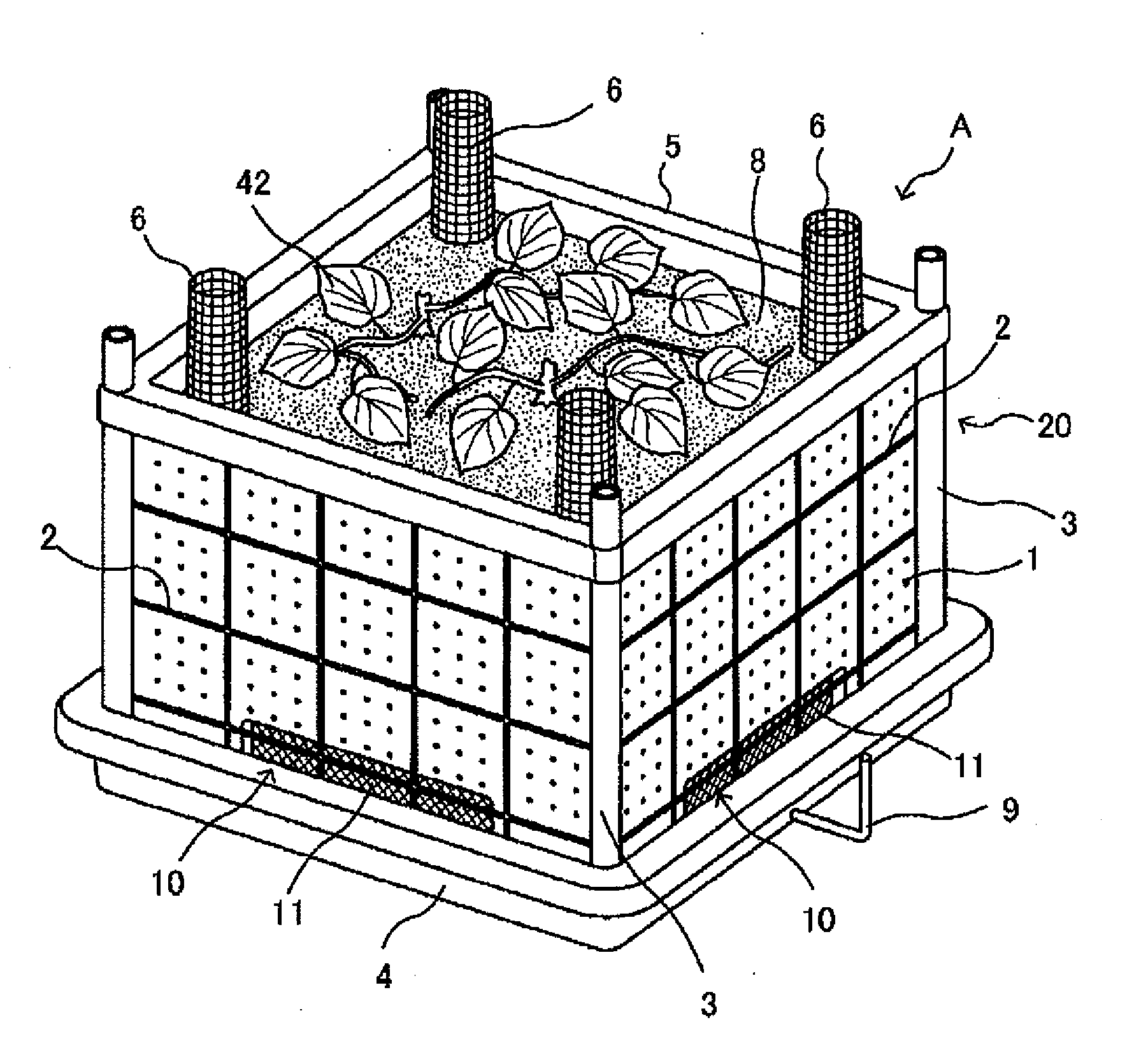
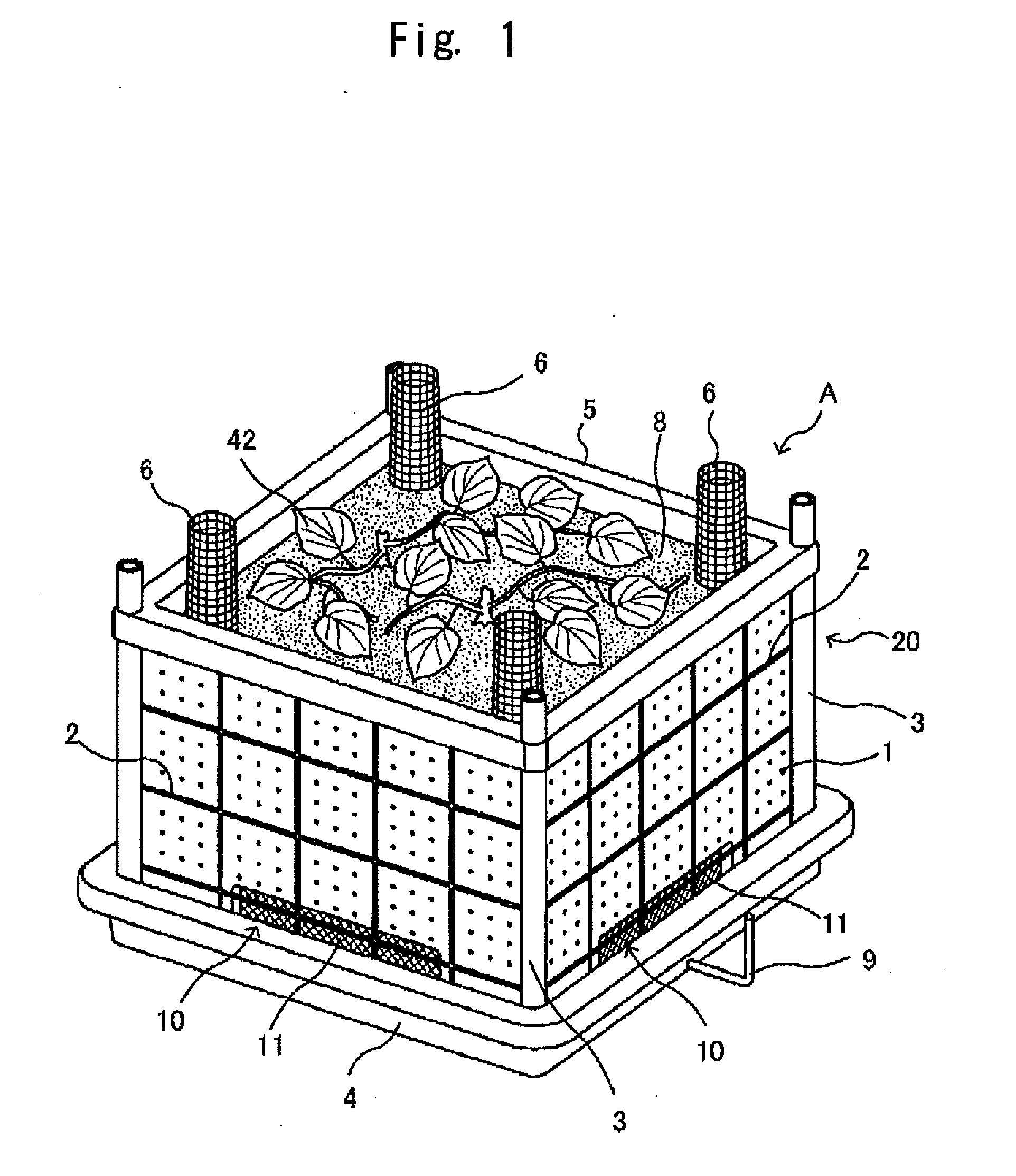
[0106]As also shown in FIG. 8, the fixing device D according to the fourth embodiment, in an approximately similar way as the above-mentioned fixing device A and fixing device B, is constituted of a box part 40 and a water reservoir tray 4, and plants sweet potatoes 46 in a soil 41 held inside.

[0107]To be more specific, the fixing device D is configured to arrange a water purification equipment 42 as an air and water flow-through unit including an aeration passage 6 in the water reservoir tray 4 having a shape of circular cylinder with a bottom, and to ar...


PUM


Abstract

There are provided a device for fixing biomass-based solar heat and carbon dioxide gas with a similarity to containerized culture having high crop productivity, which is capable of fixing carbon dioxide gas highly efficiently, while being compact and easily managed, and a house equipped with the fixing device having an energy circulation system. The fixing device for biomass-based solar heat and carbon dioxide gas is configured to include an air intake unit which takes air into a box, a mesh-like air and water flow-through unit laid in the bottom of the box that is configured to be open to the atmosphere, a water reservoir tray on which the box is mounted, and cultivation soil which is held inside the box. Further, in the house relating to the present invention, the fixing device for biomass-based solar heat and carbon dioxide gas is arranged in an area that gets a lot of sunshine.

Description


Claims


Application Information

Patent Timeline
Owner PLUS KAKEN INNOVATE LABO
Why Eureka
Try Eureka