Clean transition between ccm and dcm in valley current mode control of dc-to-dc converter

a dc-to-dc converter and valley current technology, applied in the direction of dc-dc conversion, power conversion systems, instruments, etc., can solve problems such as asociating noise in the output of converters

Inactive Publication Date: 2011-06-23
ANALOG DEVICES INT UNLTD
View PDF5 Cites 27 Cited by
  • Summary
  • Abstract
  • Description
  • Claims
  • Application Information

AI Technical Summary

Problems solved by technology

Transitions between these two modes of operation may cause instability and associate noise in the output of the converter.

Method used


Image

  • Clean transition between ccm and dcm in valley current mode control of dc-to-dc converter
  • Clean transition between ccm and dcm in valley current mode control of dc-to-dc converter
  • Clean transition between ccm and dcm in valley current mode control of dc-to-dc converter

Examples


Embodiment Construction

[0019]Illustrative embodiments are now discussed. Other embodiments may be used in addition or instead. Details that may be apparent or unnecessary may be omitted to save space or for a more effective presentation. Conversely, some embodiments may be practiced without all of the details that are disclosed.

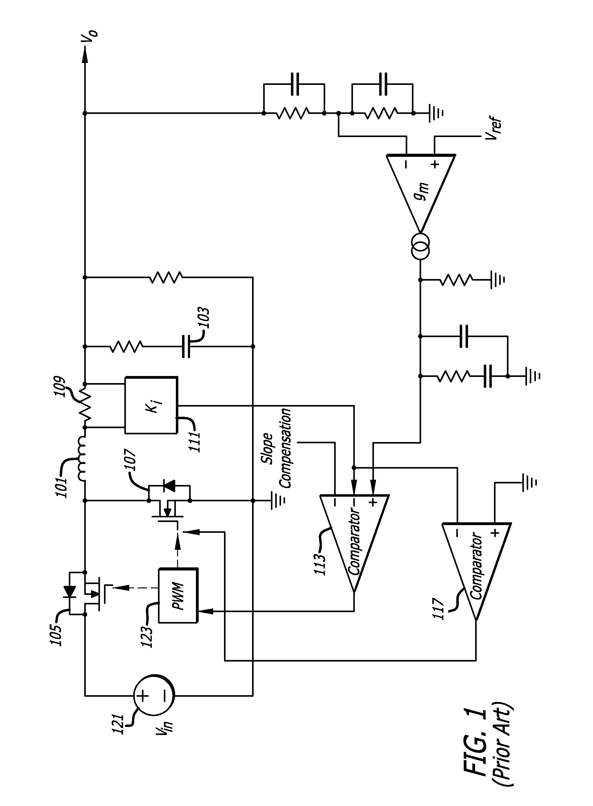
[0020]FIG. 1 illustrates a prior art DC-to-DC converter which uses valley current mode control.

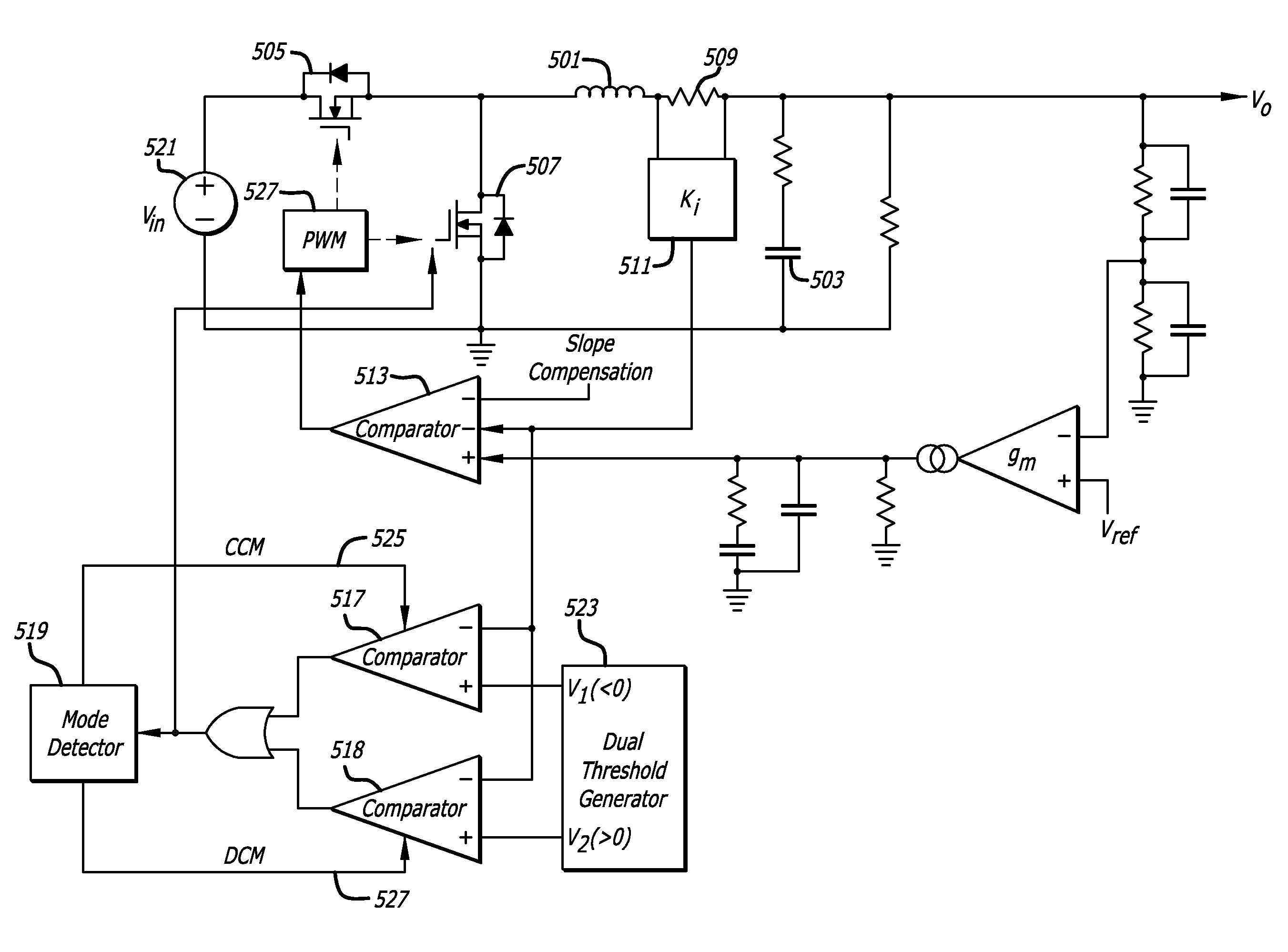
[0021]As illustrated in FIG. 1, the prior art DC-to-DC converter may include an inductor 101, a capacitor 103, an electronic switching system which may include electronic switches 105 and 107, an electronic control system which may include a current sensing system which may include a resistor 109 and a scaler 111, a comparator system which may include a forward current comparator 113 and a reverse current comparator 117, and a pulse-width modulator 123. As illustrated in FIG. 1, the prior art DC-to-DC converter may include other components, such as components that may provide network comp...


PUM


Abstract

A valley current mode DC-to-DC converter may include an electronic control system configured to cause the DC-to-DC converter to operate under a continuous current mode and a discontinuous current mode. The electronic control system may include a current sensing system configured to sense current traveling through an inductance, a dual threshold generator configured to generate a first and a different second threshold, and a comparator system configured to compare current sensed by the current sensing system with the first threshold when the DC-to-DC converter is operating in the continuous current mode and with the second threshold when the DC-to-DC converter is operating in the discontinuous current mode.

Description

BACKGROUND[0001]1. Technical Field[0002]This disclosure relates to DC-to-DC converters which use valley current mode control.[0003]2. Description of Related Art[0004]Switching DC-to-DC converters may regulate output voltage by cyclically delivering energy during a regulated duty cycle into an inductor using a switching network. The duty cycle may be regulated to keep the output voltage constant, notwithstanding variation in the load and / or input voltage.[0005]Current-mode control has been used to regulate the duty cycle. One type of current mode control is known as valley current mode control. Current sensing may take place during the interval of the down slope of current through the inductor or the Bottom MOSFET.[0006]The controller may at times cause the DC-to-DC converter to operate in a continuous current mode (“CCM”) during which current may always be flowing through the inductor. The controller may at other times cause the DC-to-DC converter to operate in a discontinuous curre...

Claims


Application Information

Patent Timeline
Patent Type & Authority Applications(United States)
IPC IPC(8): G05F1/618
CPCH02M3/156H02M2001/0003H02M3/158H02M1/0003
Inventor REN, HONG
Owner ANALOG DEVICES INT UNLTD
Why Eureka
Try Eureka