Appliance having a user grace period for reinitiating operating when in demand response energy mode

a technology of demand response and grace period, applied in the field of energy management, can solve the problems of no active control, many utilities are currently experiencing a shortage of electric generating capacity, etc., and achieve the effect of reducing power consumption and reducing power consumption of the utensils

Active Publication Date: 2011-06-23
HAIER US APPLIANCE SOLUTIONS INC
View PDF4 Cites 51 Cited by
  • Summary
  • Abstract
  • Description
  • Claims
  • Application Information

AI Technical Summary

Benefits of technology

[0005]According to another aspect, an appliance comprises a power consuming feature / function and a controller operatively connected to the power consuming feature / function. The controller is configured to receive and process a signal indicative of current state of an associated utility. The controller operates the appliance in at least one of a normal operating mode and an energy savings mode, in response to the received signal. The controller is configured to at least one of selectively adjust and disable the power consuming feature / function to reduce power consumption of the appliance in the energy savings mode. If the power consuming feature / function is activated and the appliance switches from the normal operating mode to the energy savings mode and a user then disables the power consuming feature / function, the controller is configured to provide a period of time for the user to reactive the power consuming feature / function and continue normal operation of the power consuming feature / function in the energy savings mode. If the power consuming feature / function is activated and the appliance switches from the normal operating mode to the energy savings mode and the power consuming feature / function is adjusted to reduce power consumption, the controller is configured to provide a period of time for the user to override the adjustment and continue normal operation of the power consuming feature / function in the energy savings mode.

Problems solved by technology

Many utilities are currently experiencing a shortage of electric generating capacity due to increasing consumer demand for electricity.
Currently utilities generally charge a flat rate, but with increasing cost of fuel prices and high energy usage at certain parts of the day, utilities have to buy more energy to supply customers during peak demand.
Presently, to take advantage of the lower cost of electricity during off-peak times, a consumer typically manually operates power consuming devices during the off-peak times. This is undesirable because the consumer may not always be present in the home to operate the power consuming devices during off-peak hours.
This is also undesirable because the consumer is required to manually track the current time to determine what hours are off-peak and on-peak.
However, there is no active control beyond the mere on / off switching and / or adjustment.
One difficulty of this method is that if the consumer is using the power consuming device as the utility switches to the peak demand and then inadvertently turns the power consuming device off, the energy supply to the power consuming device will be switched off and / or adjusted by the controller.

Method used


Image

  • Appliance having a user grace period for reinitiating operating when in demand response energy mode
  • Appliance having a user grace period for reinitiating operating when in demand response energy mode
  • Appliance having a user grace period for reinitiating operating when in demand response energy mode

Examples


Embodiment Construction

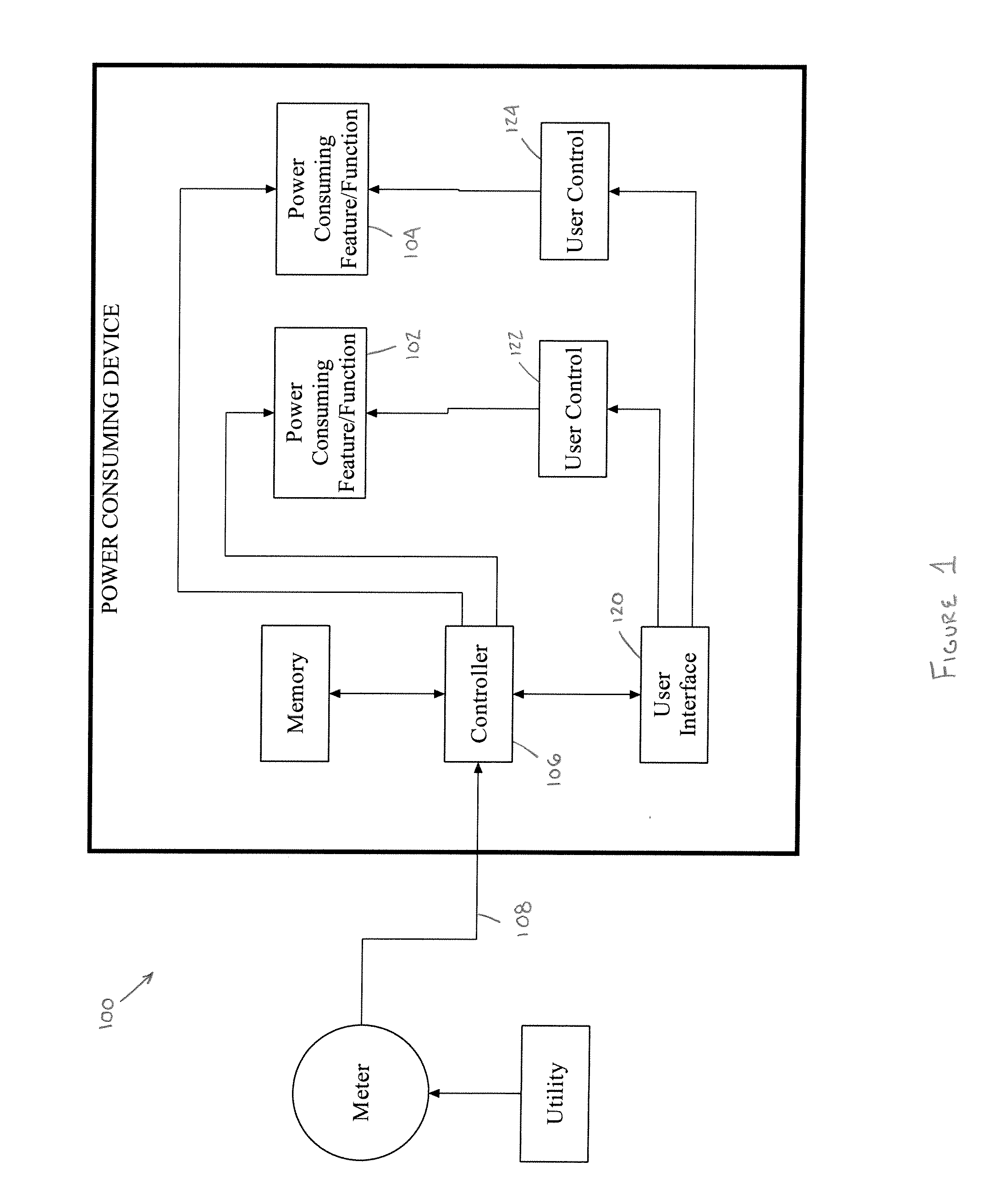
[0011]It should, of course, be understood that the description and drawings herein are merely illustrative and that various modifications and changes can be made in the structures disclosed without departing from the present disclosure. Referring now to the drawings, wherein like numerals refer to like parts throughout the several views, FIG. 1 schematically illustrates a power consuming device 100 according to one aspect of the present disclosure. The power consuming device 100 comprises one or more power consuming features / functions 102, 104. A controller 106 is operatively connected to each of the power consuming features / functions. The controller 106 can include a memory and a micro computer on a printed circuit board which is programmed to selectively control the energization of the power consuming features / functions. The controller 106 is configured to receive and process a signal 108 indicative of a utility state, for example, availability and / or current cost of supplied ener...


PUM

PropertyMeasurementUnit
energyaaaaaaaaaa
current consumptionaaaaaaaaaa
poweraaaaaaaaaa

Abstract

An energy consuming device comprises a power consuming feature/function and a controller operatively connected to the power consuming feature/function. The controller is configured to operate the device including the power consuming feature/function in one of a plurality of operating modes, including at least a normal operating mode during an associated off-peak demand period of an associated energy supplying utility and an energy savings mode during an associated peak demand period of the associated energy supplying utility. The controller is configured to provide a user a grace period during the associated peak demand period to allow the user to change the operating mode of the power consuming feature/function from the energy savings mode to another operating mode including the normal operating mode thereby allowing additional use of the power consuming feature/function during the associated peak demand period.

Description

BACKGROUND[0001]The present disclosure relates to energy management, and more particularly to power consuming device control methods and electrical energy consumption systems.[0002]Many utilities are currently experiencing a shortage of electric generating capacity due to increasing consumer demand for electricity. Currently utilities generally charge a flat rate, but with increasing cost of fuel prices and high energy usage at certain parts of the day, utilities have to buy more energy to supply customers during peak demand. Consequently, utilities are charging higher rates during peak demand. If peak demand can be lowered, then a potential huge cost savings can be achieved and the peak load that the utility has to accommodate is lessened. In order to reduce high peak power demand, many utilities have instituted time of use metering and rates which include higher rates for energy usage during on-peak times and lower rates for energy usage during off-peak times. As a result, consume...

Claims


Application Information

Patent Timeline
Patent Type & Authority Applications(United States)
IPC IPC(8): H02J3/12
CPCH02J3/14Y04S20/222Y02B70/3225H05B1/0266H02J2310/60
Inventor BURT, ASHLEY WAYNEFINCH, MICHAEL F.GAWRON, GREGORY F.JOHNSON, MARK DAVISWEBER, JEFFREY S.
Owner HAIER US APPLIANCE SOLUTIONS INC
Why Eureka
Try Eureka