Variable attenuator having stacked transistors

a technology of variable attenuator and transistor, which is applied in the field of attenuators, can solve the problems of low resolution of dca attenuator, high degree of distortion of type of vca, and inability to dynamically control the attenuation range of passive attenuators, so as to achieve low distortion, wide bandwidth, and increase the width of transistors

Active Publication Date: 2011-06-23
QORVO US INC
View PDF11 Cites 45 Cited by
  • Summary
  • Abstract
  • Description
  • Claims
  • Application Information

AI Technical Summary

Benefits of technology

[0011]The present disclosure relates generally to variable attenuators and temperature compensation attenuators. More specifically, the disclosure relates to variable attenuators and temperature compensation attenuators having dynamic attenuation ranges and/or wide bandwidth, and low distortion. In one embodiment, a variable attenuator includes an attenuation circuit having a first series connected attenuation circuit segment and a first shunt connected attenuation circuit segment. Additional series connected and/or shunt connected attenuation circuit segments may also be provided so that the attenuation circuit can be arranged as a Tee or Pi type attenuator if desired. Each attenuation circuit segment in the attenuation circuit includes a plurality of stacked transistors. The plurality of stacked transistors in each attenuation circuit segment are coupled to provide the attenuation circuit segment with a variable impedance level having a continuous impedance range. By having a plurality of stacked transistors in each attenuation circuit segment, the signal being attenuated by the attenuation circuit is distributed among each of the transistors in the stack. Furthermore, the width of the transistors may be increased to compensate for the stacking of serial device. As a result, the stack of transistors in each attenuation circuit segment can thus reduce distortion A control circuit may be operably associated with each of the plurality of stacked transistors to control the variable impedance level of each of the attenuation circuit segments. The control circuit controls the variable impedance level in each attenuation circuit segment based on the signal level of the attenuation control signal. In this manner, the variable impedance levels of each of the attenuation circuit segments in the attenuation circuit may be controlled so that the variable attenuator is set at a desired impedance level.
[0012]In another embodiment, a temperature compensation attenuator includes an attenuation circuit having a first series connected attenuation circuit segment and a first shunt connected attenuation circuit segment. As in the variable attenuator described above, additional series connected and/or shunt connected attenuation circuit segments may also be provided so that the attenuation circuit can be arranged as a Tee or Pi type attenuator if desired. Each attenuation circuit segment in the attenuation circuit includes a plurality of stacked transistors. The plurality of stacked transistors in each attenuation segment is coupled to attenuate an input signal. The plurality of stacked transistors may be set by a control circuit to a constant impedance level that provides attenuation at a desired value. In the alternative, the plurality of stacked transistors may be configured by the control circuit to provide each attenuation circuit segment with a variable

Problems solved by technology

Unfortunately, passive attenuators are not dynamic and modifying their impedance levels requires physically changing the passive components in the passive attenuator.
However, since the impedance level of the digitally controlled attenuator can only vary in accordance with the attenuation being introduced by the passive components coupled to the transistors, the impedance levels of the DCA are discrete and thus the attenuation range of the DCA suffers from low resolution.
Unfortunately, these types of VCA's suffer from a high degree

Method used


Image

  • Variable attenuator having stacked transistors
  • Variable attenuator having stacked transistors
  • Variable attenuator having stacked transistors

Examples


Embodiment Construction

[0058]The embodiments set forth below represent the necessary information to enable those skilled in the art to practice the embodiments and illustrate the best mode of practicing the embodiments. Upon reading the following description in light of the accompanying drawing figures, those skilled in the art will understand the concepts of the disclosure and will recognize applications of these concepts not particularly addressed herein. It should be understood that these concepts and applications fall within the scope of the disclosure and the accompanying claims.

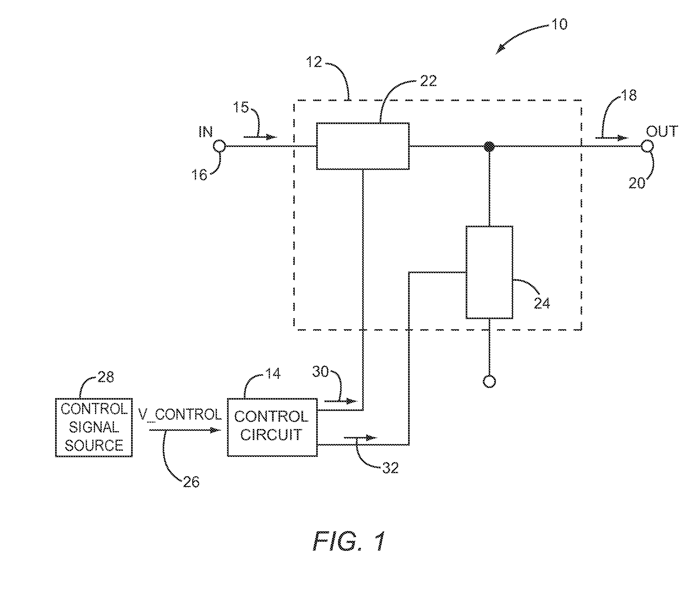
[0059]The present disclosure relates generally to variable attenuators and methods of operating the same. More particularly, the disclosure describes variable attenuators that have dynamic attenuation ranges and / or high bandwidth and low distortion. FIG. 1 illustrates a variable attenuator 10 having an attenuation circuit 12 and a control circuit 14. The attenuation circuit 12 attenuates an input signal 15 received from the i...


PUM


Abstract

In one embodiment, a variable attenuator is disclosed having an attenuation circuit and a control circuit. The attenuation circuit may include a first series connected attenuation circuit segment and a shunt connected attenuation circuit segment, as well as additional attenuation circuit segments. Each attenuation circuit segment includes a stack of transistors that are coupled to provide the attenuation circuit segment with a variable impedance level having a continuous impedance range. In this manner, the control circuit may be operably associated with the stack of transistors in each attenuation circuit segment to control the variable attenuation level of the variable attenuator.

Description

RELATED APPLICATIONS[0001]This application claims the benefit of provisional patent application Ser. No. 61 / 289,883, filed Dec. 23, 2009, and provisional patent application Ser. No. 61 / 384,763, filed Sep. 21, 2010, the disclosures of which are hereby incorporated herein by reference in their entireties.FIELD OF THE DISCLOSURE[0002]The present disclosure relates to attenuators configured to have variable impedance levels and methods of operating the same. The present disclosure also relates to attenuators that compensate for temperature changes during operation of the attenuator. The present disclosure also related to attenuators having variable impedance levels that are controlled based on a temperature.BACKGROUND[0003]Attenuators are designed to introduce a known loss between two or more nodes in a circuit. Often, these devices are utilized in radio frequency (RF) circuits, audio equipment, and measuring instruments to lower voltage, dissipate power, and / or for impedance matching. ...

Claims


Application Information

Patent Timeline
IPC IPC(8): H03H11/02
CPCH03L5/00H03H11/245H01L2224/48091H01L2224/48137H01L2224/48247H01L2224/49112H01L2224/0603H01L2224/49113H01L2224/05553H01L2224/05554H01L2924/181H01L2924/00014H01L2924/00012
Inventor GRANGER-JONES, MARCUSNELSON, BRADFRANZWA, ED
Owner QORVO US INC
Why Eureka
Try Eureka