
Holographic display device comprising magneto-optical spatial light modulator

a holographic display and spatial light modulator technology, applied in holographic processes, color television, television systems, etc., can solve the problems of slm not providing high-resolution phase modulation, difficulty in generating frame rate of holographic displays, and large visibility regions, so as to minimize pixel crosstalk, minimize pixel crosstalk, and soft aperture

Inactive Publication Date: 2011-06-23
SEEREAL TECHNOLOGIES
View PDF8 Cites 85 Cited by
  • Summary
  • Abstract
  • Description
  • Claims
  • Application Information

AI Technical Summary

Benefits of technology

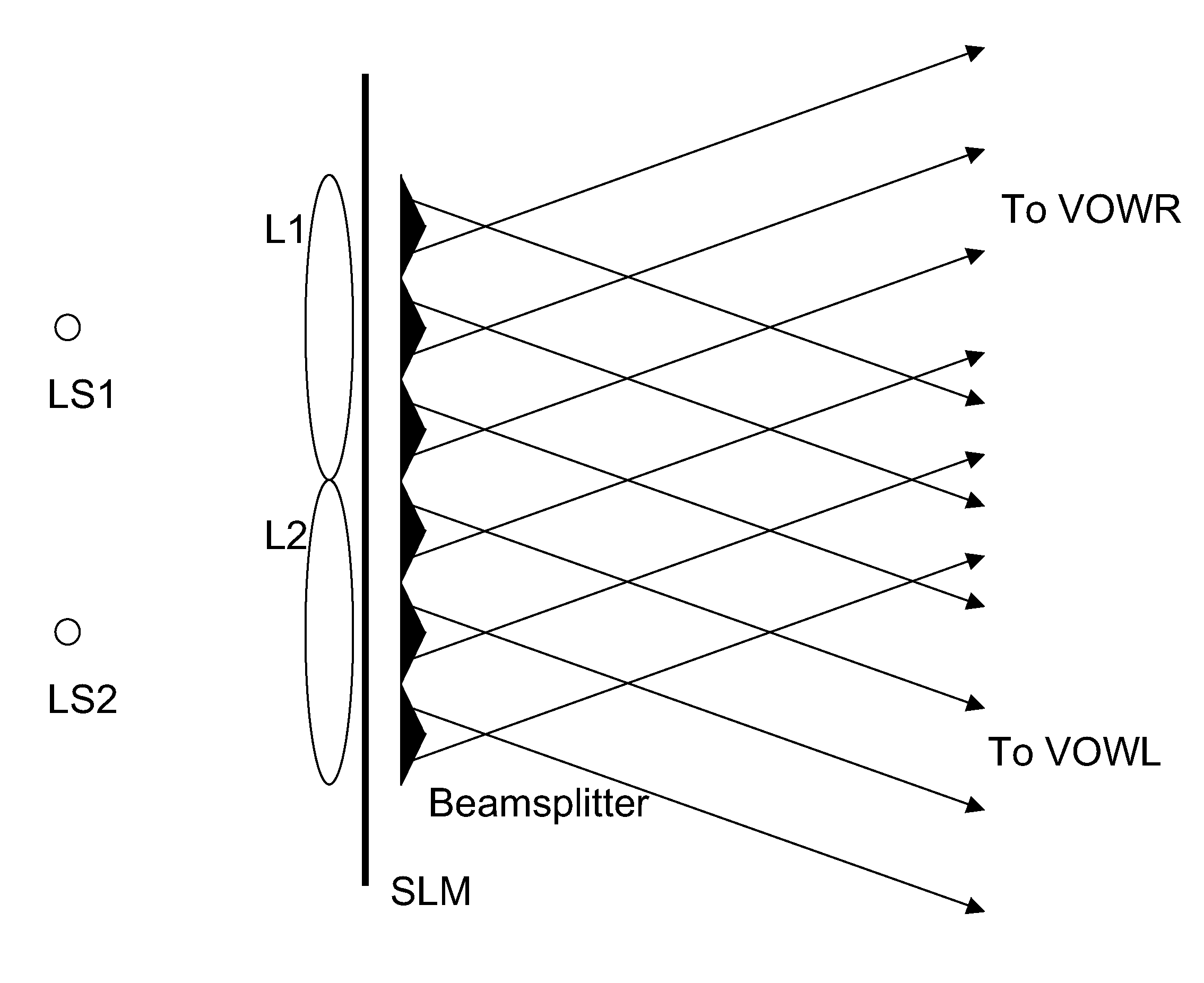
In a further aspect there is provided a compact combination of two MOSLMs which can be used to modulate the amplitude and the phase of light in sequence and in a compact way such that a complex number, which consists of an amplitude and a phase, can be encoded in the transmitted light, on a pixel by pixel basis. The compact combination may be one in which there is no requirement for imaging optics. The compact combination may be one in which the device elements are less than 3 cm in thickness in total. The compact combination may be one in which there are soft apertures for the pixels of the device. The compact combination may be one in which the two MOSLMs are directly joined or glued together, with aligned pixels. The compact combination may be one in which the separation of the two MOSLMs is less than or equal to the order of 10 microns to 100 microns. The compact combination may be one in which the diffraction of light passing from one MOSLM to the other MOSLM is in the Fresnel diffraction regime, not the far-field diffraction regime. The compact combination may be one in which there is a lens array between the two MOSLMs such that each lens images a pixel of the first SLM on to the respective pixel of the second SLM. The compact combination may be one in which the aperture width of the first MOSLM pixels is such that it minimizes pixel cross talk. The compact combination may be one in which the aperture width of the first MOSLM pixels is such that it minimizes pixel cross talk in the Fraunhofer diffraction regime to the pixels of the second MOSLM. The compact combination may be one in which a fibre optic faceplate is used to image the pixels of the first MOSLM onto the pixels of the second MOSLM.

Problems solved by technology

Here, a visibility region, which would typically be rather large, is limited to the locally positioned virtual observer windows.
However, difficulties with the frame rate which can be generated by a holographic display are encountered, especially if more than one viewer of the display is considered.
Known fast micro-electromechanical systems (MEMS)-SLM do not provide high-resolution phase modulation.
Hence known devices have severe difficulty in displaying holographic images to multiple observers with full complex holographic encoding, particularly when the images are in colour.
Prior-art Faraday-effect magneto-optic SLMs (MOSLMs) are known but these only modulate the amplitude of the transmitted light, and have not been used in generating holograms.

Method used


Image

  • Holographic display device comprising magneto-optical spatial light modulator
  • Holographic display device comprising magneto-optical spatial light modulator
  • Holographic display device comprising magneto-optical spatial light modulator

Examples


Embodiment Construction

Various implementations will now be described.

A. Holographic Display Device with a Magneto-Optical SLM

This implementation provides a holographic display device with a magneto-optical SLM, the combination being capable of generating a three dimensional image under suitable illumination conditions. The display may be illuminated by multiple light sources or by a single light source. The holographic display may be used in a television, a monitor, a laptop computer, a mobile phone, a PDA, a digital music player, or any other device in which displays are commonly used.

This implementation relates to a SLM for modulation of light, i.e. modulation of amplitude or phase, or a combination of amplitude and phase. Specifically, it relates to a SLM based on modulation of light by the Faraday effect. The SLM may be used in a holographic display.

The Faraday effect can manifest itself as a rotation of linearly polarized light in a medium upon application of a magnetic field in the direction of ligh...


PUM


Abstract

A holographic display device comprising at least one magneto-optical spatial light modulator (MOSLM). The holographic display device may comprise a first MOSLM and a second MOSLM, the first and second MOSLMs encoding a hologram and a holographic reconstruction being generated by the device. An advantage of the device is fast encoding of holograms.

Description

BACKGROUND OF THE INVENTION1. Field of the InventionThe invention relates to a holographic display device on which computer-generated video holograms (CGHs) are encoded, the display comprising at least one magneto-optical SLM. The display generates three dimensional holographic reconstructions.2. Technical BackgroundComputer-generated video holograms (CGHs) are encoded in one or more spatial light modulators (SLMs); the SLMs include controllable cells. The cells modulate the amplitude and / or phase of light by encoding hologram values corresponding to a video-hologram. The CGH may be calculated e.g. by coherent ray tracing, by simulating the interference between light reflected by the scene and a reference wave, or by Fourier or Fresnel transforms. An ideal SLM would be capable of representing arbitrary complex-valued numbers, i.e. of separately controlling the amplitude and the phase of an incoming light wave. However, a typical SLM controls only one property, either amplitude or ph...

Claims


Application Information

Patent Timeline
Patent Type & Authority Applications(United States)
IPC IPC(8): H04N5/89H01J9/00
CPCG03H1/02G03H2210/20G03H1/2294G03H2001/0224G03H2001/2218G03H2001/2242G03H2001/2292G03H2001/2297G03H2001/261G03H2001/264G03H2001/303G03H2222/22G03H2222/34G03H2222/35G03H2223/19G03H2225/20G03H2225/22G03H2225/33G03H2225/55G03H2225/60G03H2226/05G03H2227/02G03H2227/05G03H2240/61H04N5/66G03H2210/30G03H1/2249G03H1/2205
Inventor KROLL, BOLEISTER, NORBERTSCHWERDTNER, ARMINHAUSSLER, RALF
Owner SEEREAL TECHNOLOGIES
Learn More