
Digital integrated antenna array for enhancing coverage and capacity of a wireless network

a wireless network and integrated antenna technology, applied in the field of wireless networking, can solve the problems of increasing the development cost of base stations and the cost of transmitted data, and achieve the effect of increasing the degree of freedom and increasing the flexibility of control

Inactive Publication Date: 2011-06-23
VIAVI SOLUTIONS INC
View PDF8 Cites 124 Cited by
  • Summary
  • Abstract
  • Description
  • Claims
  • Application Information

AI Technical Summary

Benefits of technology

[0020]In order to solve the above-noted deficiency in the art, it is proposed to integrate a passive antenna array with radio transceivers in a single physical package and to distribute the design to increase the degrees of freedom to offer more control flexibility.

Problems solved by technology

A key factor in network design is the cost per bit of transmitted data.
Obviously, per user beamforming requires the development of more expensive base stations that provide meaningful business only in specific cases.

Method used


Image

  • Digital integrated antenna array for enhancing coverage and capacity of a wireless network
  • Digital integrated antenna array for enhancing coverage and capacity of a wireless network
  • Digital integrated antenna array for enhancing coverage and capacity of a wireless network

Examples


Embodiment Construction

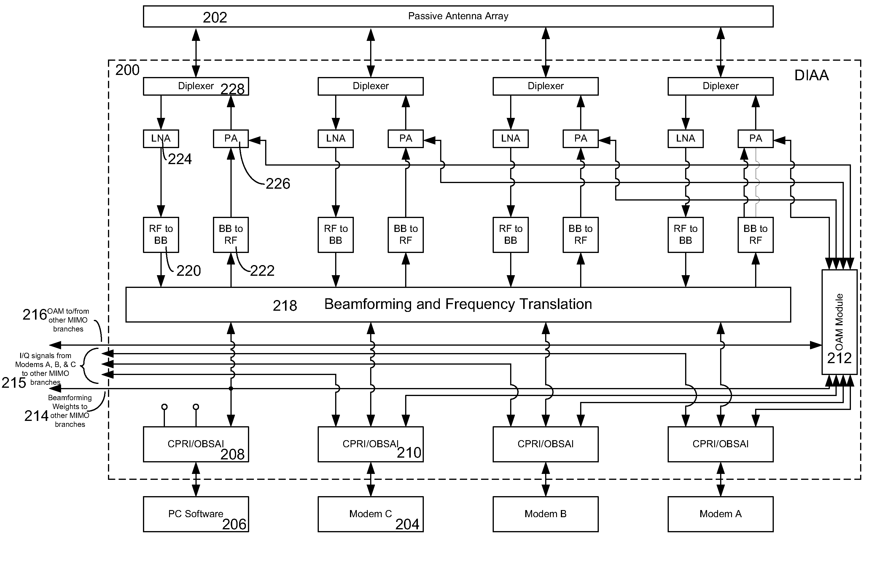
[0036]FIGS. 2A and 2B illustrate an exemplary digital integrated antenna array system for carrying out an embodiment of the present invention. FIG. 2A illustrates a general high-level implementation of the digital integrated antenna array (“DIAA”) and represents a single MIMO branch of a DIAA system, while FIG. 2B shows a more detailed implementation of the DIAA of FIG. 2A. An exemplary implementation of a 2×N MIMO DIAA, essentially including multiples of the hardware of FIGS. 2A and 2B, is illustrated FIG. 6 and will be discussed below. Additionally, exemplary implementations of 4×N MIMO DIAAs, essentially including multiples of the hardware of FIGS. 2A and 2B, are illustrated by FIGS. 7-11 and will be discussed below. In discussing a 2×N or a 4×N system DIAA, it should be noted that N is the number of transceivers at the subscriber station, a detailed discussion of which is outside the scope of the present application.

[0037]In FIG. 2A, one or more modems 204, such as, for example,...


PUM


Abstract

An embodiment of the invention relates to a digital integrated antenna array system having one or more antenna modules, one or more transceiver modules each having one or more signal processing paths for transmitting data to or receiving data from the one or more antenna modules, a signal processing unit able to process data for each the one or more signal processing paths of the one or more transceiver modules such that the data transmitted from the one or more transceiver modules to the one or more antenna modules is radiated by the one or more antenna modules into one or more radiation patterns.

Description

BACKGROUND OF THE INVENTION[0001]1. Field of the Invention[0002]The present invention relates generally to the field of wireless networking, and more specifically to using a digital integrated antenna array for enhancing coverage and capacity of a wireless network, and enabling a versatile solution for sharing antenna elements and active electronics between multiple operators servicing the same geographic area regardless of the supported base stations' multi-antenna schemes and the number of RF carriers.[0003]2. Description of the Related Art[0004]A key factor in network design is the cost per bit of transmitted data. Ideally, the cost per bit is reduced to cope with increase in demand of data rates while keeping unchanged customers' subscription fees. A partial solution to this problem comes from adopting the most spectrally efficient air interface (for example, orthogonal frequency-division multiplexing (OFDM)), and multiple input multiple output (MIMO) antenna techniques by an ad...

Claims


Application Information

Patent Timeline
IPC IPC(8): H04L5/16H04K1/10
CPCH04B7/0617H04B17/12H04B7/086
Inventor TRIGUI, HAFEDHCUTHILL, RICHARD DUNCAN
Owner VIAVI SOLUTIONS INC
Learn More