Seal and seal arrangement for confining leakage flows between adjacent components of turbo-machines and gas turbines

a technology of sealing arrangement and adjacent components, which is applied in the direction of machines/engines, liquid fuel engines, light and heating apparatus, etc., can solve the disadvantages of the multi-piece embodiment of the known seal cannot bridge larger gaps, and the sealing capacity of the known seal cannot be improved. , to achieve the effect of reducing the size of the known seal, increasing the flexibility of the sealing element, and reducing the positional stability and resistance to wear of the double-

Inactive Publication Date: 2011-06-23
ANSALDO ENERGIA IP UK LTD
View PDF12 Cites 34 Cited by
  • Summary
  • Abstract
  • Description
  • Claims
  • Application Information

AI Technical Summary

Benefits of technology

[0016]An annular seal is known from U.S. Pat. No. 5,630,593 A, in which the elastically deformable sealing element can be single-layered or multilayered and is either U-shaped in cross section with outwards bent-round end sections (FIGS. 2, 3, 4) or is E-shaped (FIGS. 6, 10) with three consecutive bent wall sections and two end sections which are bent round outwards. The sealing element can be exposed to a pressure difference in such a way that the outwards bent-round end sections are pressed more strongly against the oppositely disposed sealing surfaces of the components. The multilayered construction has a higher rigidity than the single-layered construction. In one of the material layers of the sealing element, provision may be made for slots which are spaced apart in the circumferential direction, in order to increase the flexibility of the sealing element. This seal is suitable for bridging gaps which vary relatively little in their width between two components. The sealing performance of this known seal, however, is also put at risk if the components move parallel to its sealing surfaces.
[0017]Also known from experience are so-called double-E seals which consist of two sealing elements which are E-shaped in cross section, these being interconnected by a cover strip, which is band-like in cross section, by welding or soldering. This type of seal, just like the single sealing element which is E-shaped in cross section, can bridge larger gaps than the sealing element which is C-shaped in cross section. The double-E seal is certainly less susceptible than the single-E seal to skewing or to displacement during relative movements of the components oriented parallel to the sealing surfaces. Larger relative movements of the components parallel to its sealing surfaces, however, also impair the positional stability and resistance to wear of the double-E seal so that, during larger relative movements of the components parallel to it

Problems solved by technology

Consequently, the contact regions of the sealing element are also pressed against the sealing surfaces of the components if the spring forces are no longer effective as a result of excessively large gap-widening or material fatigue of the sealing element as a consequence of constantly changing deformation of the sealing element.
Contingent upon the respective cross-sectional shape of the sealing element of the known seal, tight limits are set, however, to the elastic deformability of the sealing element so that they can only bridge such gaps which widen only a little in comparison to an initial gap width.
Both consequences—skewing and change of position of the sealing element—have a disadvantageous effect on the sealing capacity of the known seal.
However, even this multipiece embodiment of the known seal cannot bridge larger gaps than the aforementioned one-piece embodiments of the known seal.
Consequently, the sealing element can move between the two oppositely disposed walls of the groove which is U-shaped in cross section by a degree which can lead to skewing of the sealing element if the components move correspondingly.
Neither is this seal suitable for maintaining its sealing performance if a larger gap develops between the two components because the end sections of the sealing element then no longer bear, or do not bear tightly enough, against the sealing surfaces of the components.
The sealing element is elastically deformable perpendicularly to the sealing surfaces, wherein it is elastically deformable to a greater extent in this direction than, for example, a sealing ele

Method used


Image

  • Seal and seal arrangement for confining leakage flows between adjacent components of turbo-machines and gas turbines
  • Seal and seal arrangement for confining leakage flows between adjacent components of turbo-machines and gas turbines
  • Seal and seal arrangement for confining leakage flows between adjacent components of turbo-machines and gas turbines

Examples


Embodiment Construction

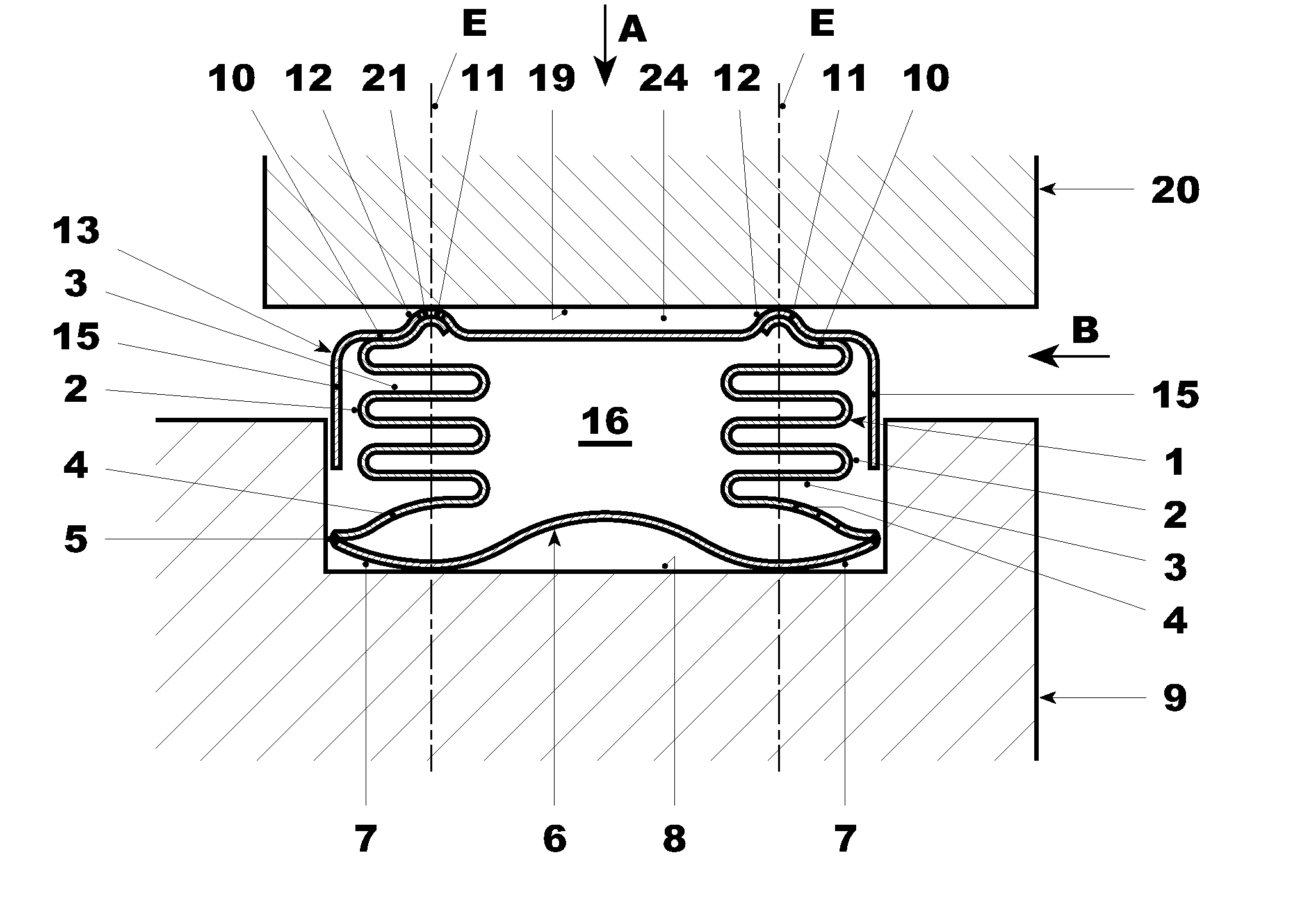
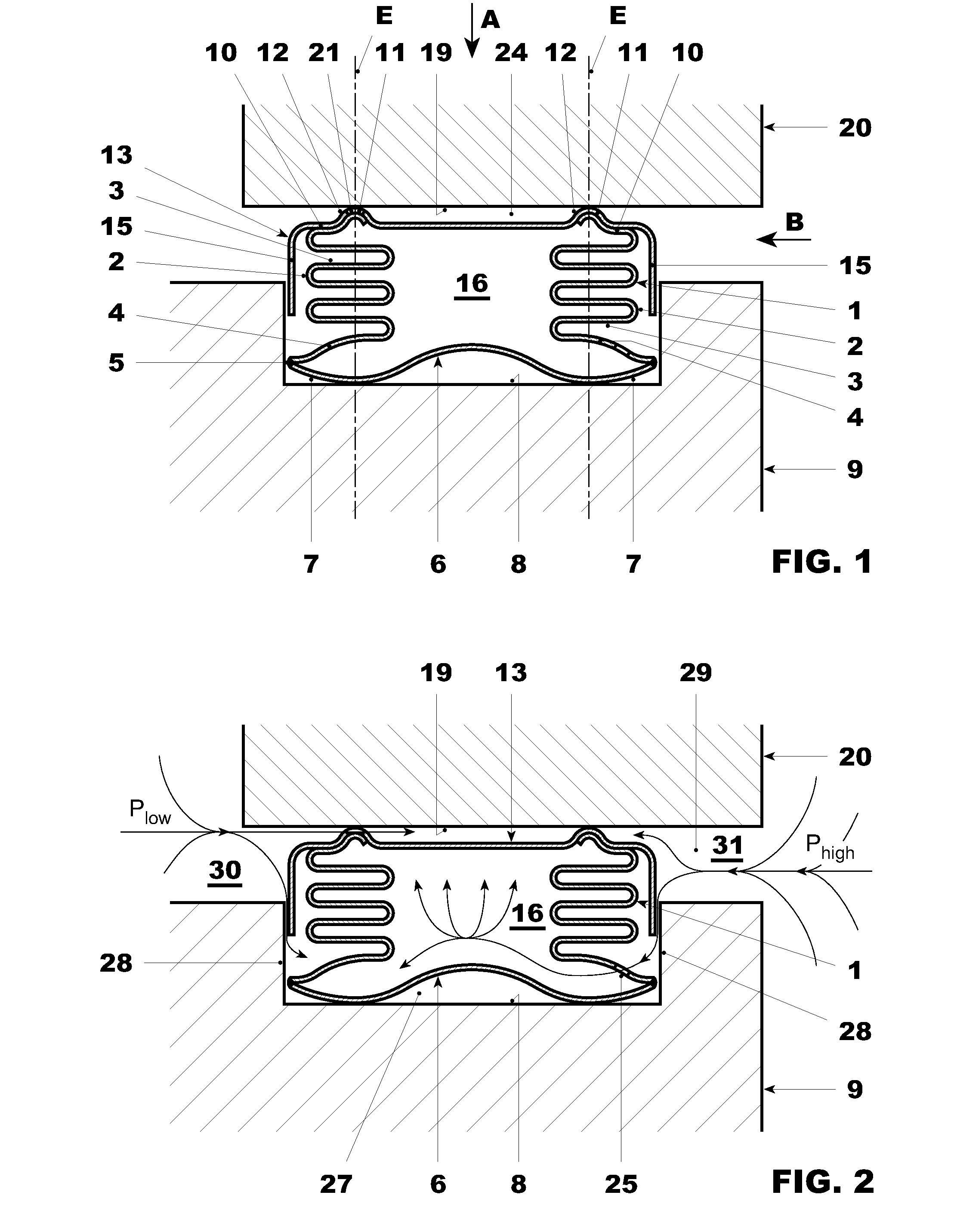
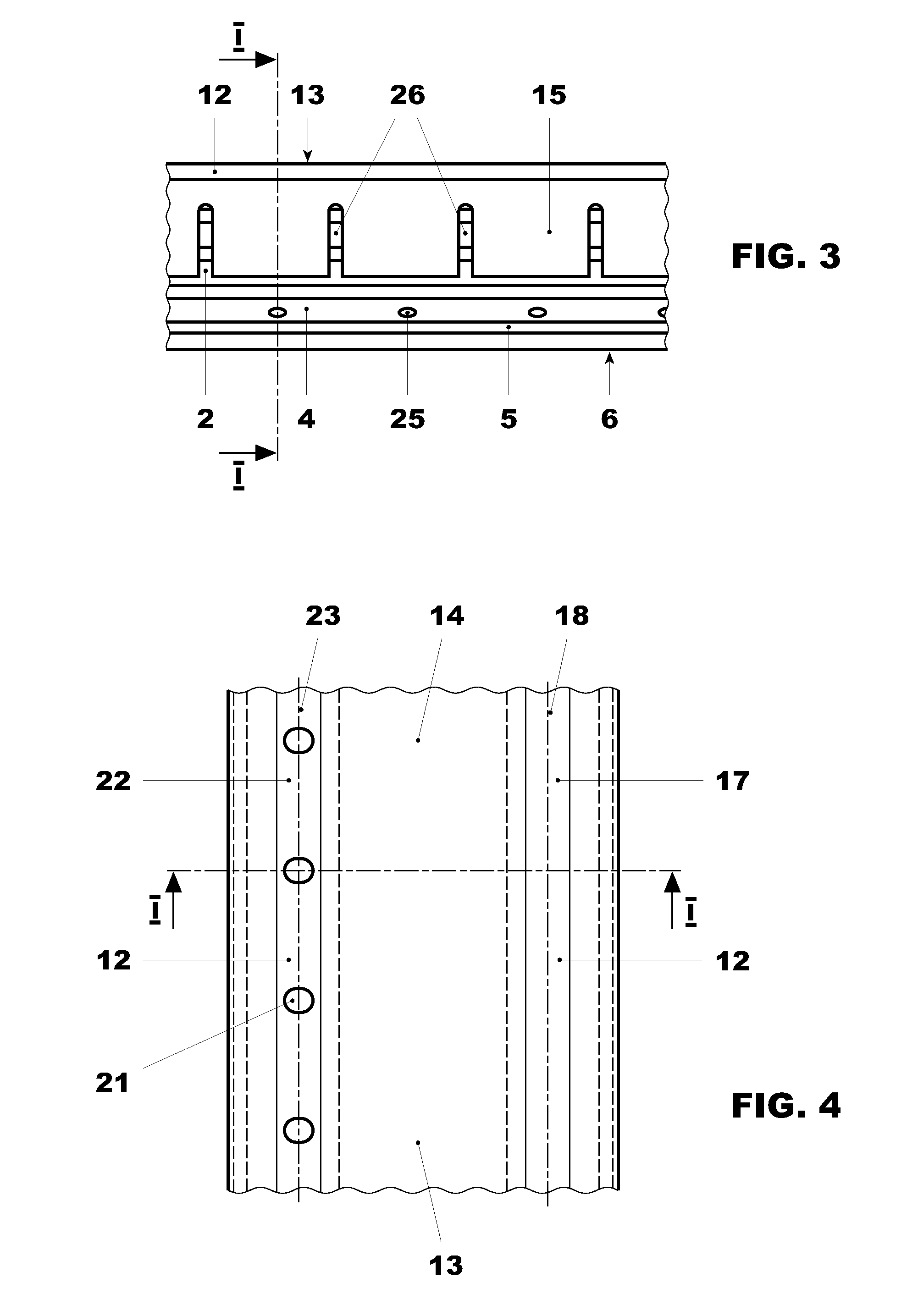
[0025]A seal, as is shown in FIGS. 1 to 4, has an elastically deformable, thin-walled sealing element 1 formed of metal which in cross section has the shape of a bent band, having two adjacent rows of consecutive bent wall sections 2 which in each case are interconnected by a transversely extending wall section 3. In the exemplary embodiment which is shown, in each row there are six bent wall sections 2 which are interconnected by all together five transversely extending wall sections 3. This number of bent wall sections 2 in each row and the associated number of transversely extending wall sections 3 are only exemplary. The number could also be greater or smaller since they have an influence upon the desired extent of the elastic deformability of the sealing element 1.

[0026]As is evident from FIG. 1, the two rows of consecutive wall sections 2 and the transversely extending wall sections 3 which connect them are arranged so that in each row all the transversely extending wall secti...


PUM


Abstract

A seal for stemming leakage flows between adjacent components (9, 20), especially of a gas turbine, has an elastically deformable, thin-walled sealing element (1) and a thin-walled cover element (13) which is U-shaped in cross section and between its legs (15) and its base (14) partially accommodates the sealing element (1). The legs (15) of the cover element (13) are arranged in the sealing arrangement, which features the seal, between two oppositely disposed walls (28) of the other component (9) in a movable manner relative to these walls (28) which, together with the sealing surface (8) of the other component (9), form a groove (27) which is U-shaped in cross section. Forces, which act laterally upon the seal, are absorbed by the cover element (13) and via the legs (15) are diverted into the other component (9) so that the integrity of the seal is maintained even in the case of lateral forces.

Description

[0001]This application is a Continuation of, and claims priority under 35 U.S.C. §120 to, International App. No. PCT / EP2009 / 057765, filed 23 Jun. 2009, and claims priority therethrough under 35 U.S.C. §§119, 365 to Swiss App. No. 01011 / 08, filed 1 Jul. 2008, the entireties of which are incorporated by reference herein.BACKGROUND[0002]1. Field of Endeavor[0003]The invention refers to a seal and sealing arrangement for stemming leakage flows between adjacent components of turbomachines, especially gas turbines, wherein the seal has an elongated, thin-walled sealing element which is elastically deformable in at least one transverse direction and which, in cross section, has the shape of a bent band.[0004]2. Brief Description of the Related Art[0005]In the installed state, the seal is arranged in a space, which is delimited by walls of the two components, in a pretensioned manner in at least one transverse direction in such a way that the at least one transverse direction extends perpen...

Claims


Application Information

Patent Timeline
IPC IPC(8): F04D29/08F16J15/16
CPCF01D11/005F16J9/20F16J9/22F05D2240/55F05D2230/232F23R2900/00012F05D2250/70F05D2250/712F05D2250/711F16J15/0893F05D2230/237
Inventor MOTZKUS, THORSTENBENZ, URS
Owner ANSALDO ENERGIA IP UK LTD
Why Eureka
Try Eureka