
Torque limiter for an oct catheter

a technology of oct catheter and torque limiter, which is applied in the direction of catheter, diagnostic recording/measuring, coupling, etc., can solve the problems of patient harm and patient harm, and achieve the effect of reducing flexur

Active Publication Date: 2011-06-23
LIGHTLAB IMAGING
View PDF69 Cites 57 Cited by
  • Summary
  • Abstract
  • Description
  • Claims
  • Application Information

AI Technical Summary

Benefits of technology

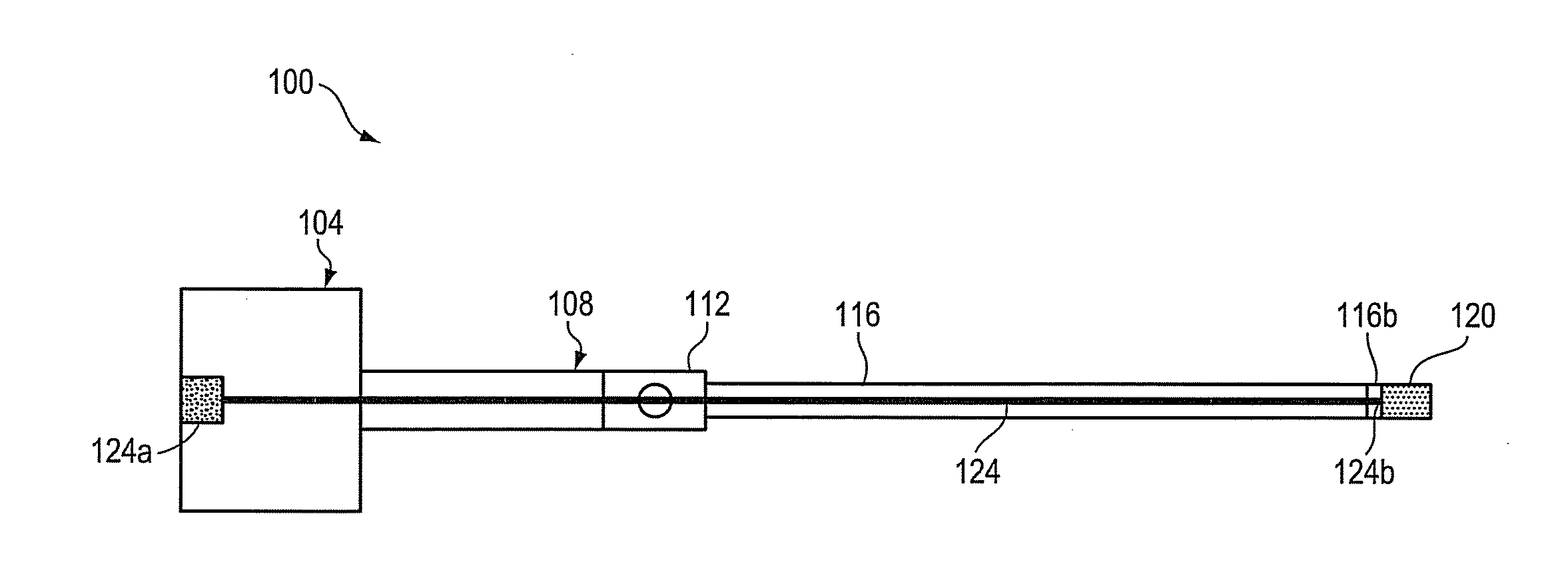
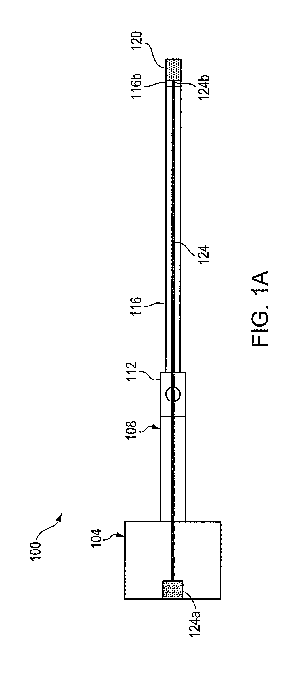
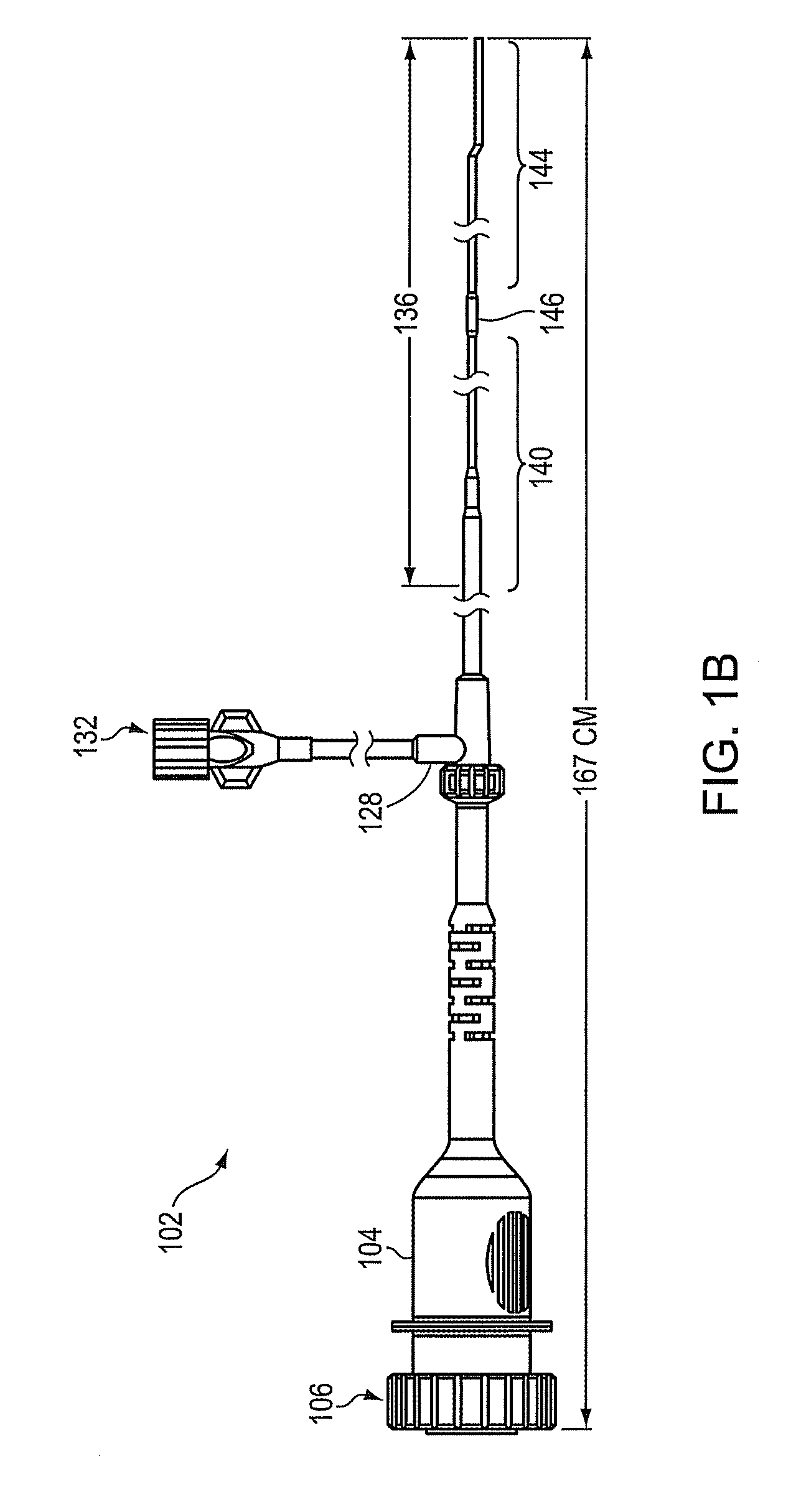
The invention relates to an apparatus for transmitting rotational force to an imaging probe. The apparatus includes a torque wire connected to the probe, and a torque limiter that breaks when the rotational force on the wire exceeds a predetermined amount. The torque limiter includes a member with a cutout that causes it to break when the force exceeds a certain level, decoupling the motor from the wire. The apparatus can be used in optical coherence tomography imaging.

Problems solved by technology

However, high torque and high speed rotation can pose a significant risk of patient harm should the OCT probe unexpectedly bind because the motor will continue spinning the torque wire, causing the torque wire to twist on itself and spin the catheter sheath which encloses the torque wire inside the body lumen, potentially causing patient harm.

Method used


Image

  • Torque limiter for an oct catheter
  • Torque limiter for an oct catheter
  • Torque limiter for an oct catheter

Examples


Embodiment Construction

[0021]The following description refers to the accompanying drawings that illustrate certain embodiments of the invention. Other embodiments are possible and modifications may be made to the embodiments without departing from the spirit and scope of the invention. Therefore, the following detailed description is not meant to limit the invention. Rather, the scope of the invention is defined by the appended claims.

[0022]The use of headings and sections in the application is not meant to limit the invention; each section can apply to any aspect, embodiment, or feature of the invention.

[0023]The order of steps in the methods described herein is immaterial so long as the invention remains operable. Moreover, two or more steps may be conducted simultaneously or in a different order than recited herein unless otherwise specified.

[0024]Where a range or list of values is provided, each intervening value between the upper and lower limits of that range or list of values is individually contem...


PUM


Abstract

An apparatus comprising a torque wire connected to an imaging probe; and a torque limiter defining a bore, a first end of the torque limiter being in mechanical communication with a motor, a second end of the torque limiter being in mechanical communication with the torque wire, the torque wire being disposed through the bore of the torque limiter. The torque limiter comprises a member defining at least one cutout which causes the torque limiter to break when rotational force on the torque wire exceeds a predetermined amount, thereby decoupling the motor from the torque wire.

Description

TECHNICAL FIELD[0001]Provided are devices and methods for limiting the rotational force imparted on an imaging probe spinning inside a patient to reduce the likelihood of an unsafe condition should the imaging probe suddenly bind.BACKGROUND[0002]Imaging of body lumens (e.g., vasculature) can require relatively high torque and relatively high rotational speeds to spin an imaging probe, such as an optical coherence tomography (OCT) probe, inside the body lumen. Generally, an OCT imaging probe is inserted in a body lumen of a patient and a motor located outside the patient spins a torque wire which is connected to the OCT imaging probe. OCT imaging systems have unique torque wire requirements as the optical fiber rotates inside of the torque wire, adding mass and stiffness. However, high torque and high speed rotation can pose a significant risk of patient harm should the OCT probe unexpectedly bind because the motor will continue spinning the torque wire, causing the torque wire to tw...

Claims


Application Information

Patent Timeline
Patent Type & Authority Applications(United States)
IPC IPC(8): F16D9/00
CPCA61B5/0062A61B5/0066A61B2019/301A61B8/12A61B8/4461A61B5/6852A61B2090/031F16D9/06
Inventor PETROFF, CHRISTOPHER
Owner LIGHTLAB IMAGING
Learn More