Drain Bolt Mounting Structure

a technology of mounting structure and bolt, which is applied in the direction of lubricant filling/draining, shaft and bearing, lubrication element, etc., can solve the problems of bolt (b>12/b>) not being easily and efficiently mounted, and having a very low standard electrode potential and high electrical corrosion risk, so as to achieve a highly sealed state and facilitate and efficiently moun

Inactive Publication Date: 2011-06-30
KAWASAKI HEAVY IND LTD
View PDF12 Cites 2 Cited by
  • Summary
  • Abstract
  • Description
  • Claims
  • Application Information

AI Technical Summary

Benefits of technology

The present invention addresses the above described conditions, and an object of the present invention is to provide a drain bolt mounting structure which allows the drain bolt to be mounted more easily and efficiently, can surely attain a highly sealed state, and can prevent the drain bolt from coming loose due to electric corrosion.

Problems solved by technology

In a case where an oil pan formed of magnesium or magnesium alloy is used to provide, for example, a lightweight engine, the oil pan is required to be subjected to an electric corrosion resistance treatment, because magnesium has a very low standard electrode potential and is likely to be electrically corroded due to contact with other metal (dissimilar metal contact).
Thus, the bolt (12) is not easily and efficiently mounted.

Method used


Image

  • Drain Bolt Mounting Structure
  • Drain Bolt Mounting Structure
  • Drain Bolt Mounting Structure

Examples


Embodiment Construction

Hereinafter, an embodiment of the present invention will be described with reference to the drawings. The stated directions are referenced from the perspective of a driver straddling a motorcycle, unless otherwise explicitly noted.

[Construction of Motorcycle]

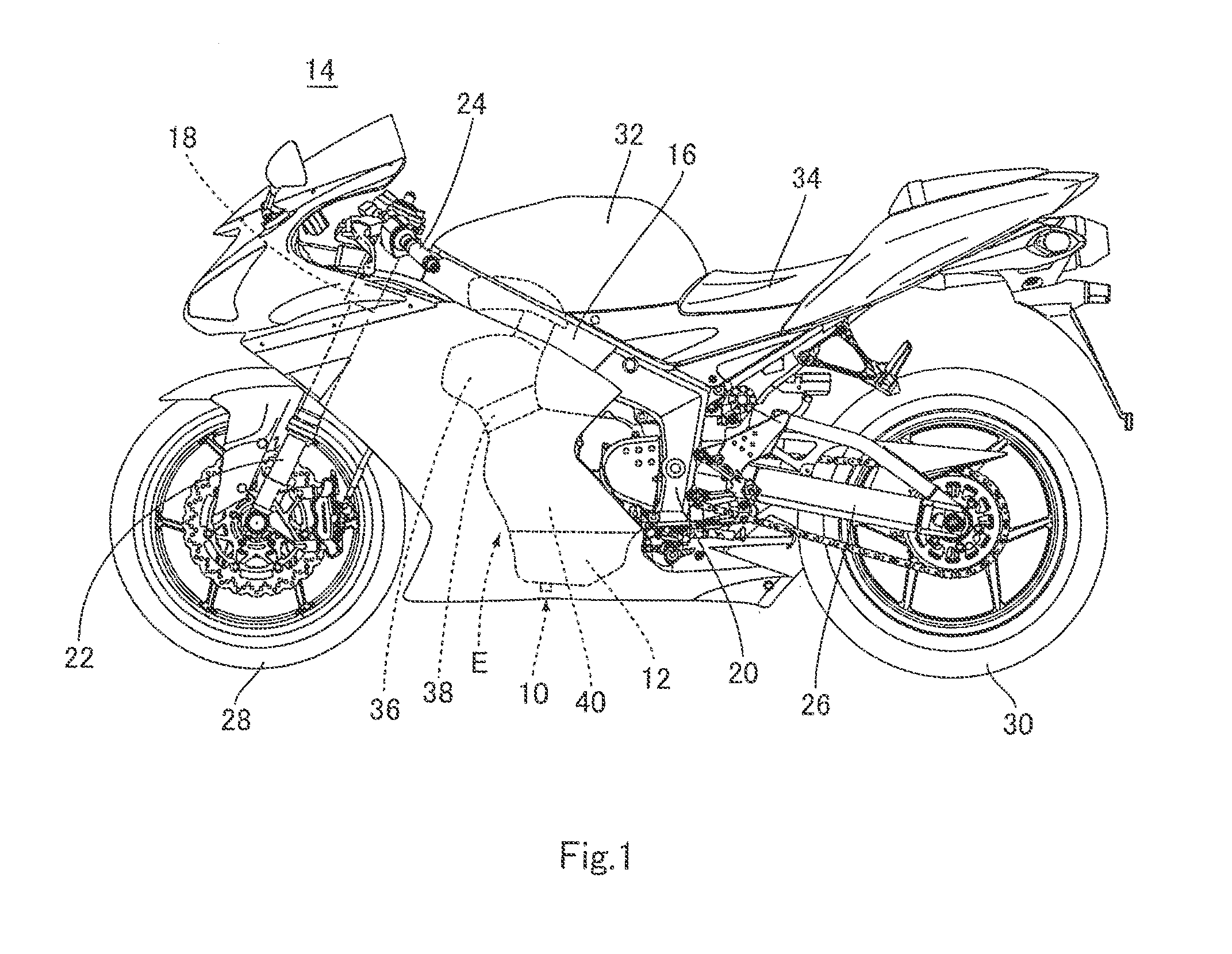
FIG. 1 is a left side view showing a construction of an entire motorcycle 14 including an oil pan 12 having a drain bolt mounting structure 10 according to the embodiment.

Referring now to FIG. 1, the motorcycle 14 includes a main frame member 16, a head pipe 18 provided at the front portion of the main frame member 16 and a pair of right and left pivot frame members 20 provided at the rear portion of the main frame member 16. A steering shaft (not shown) is rotatably inserted into the head pipe 18. A front fork 22 and a steering handle 24 are attached to the steering shaft. A pair of right and left swing arms 26 is attached to the pivot frame members 20, respectively. A front wheel 28 is mounted to the lower end portion of the f...


PUM


Abstract

A drain bolt mounting structure comprises a bottomed hole formed on an outer surface of an oil pan to extend continuously with a drain hole of the oil pan, a female thread formed on an inner peripheral surface of the drain hole; a drain bolt including a shaft portion having a male thread threadingly engageable with the female thread of the drain hole and a head portion formed at one end portion of the shaft portion; a press-in member formed of a second metal containing aluminum which has a higher standard electrode potential than a first metal forming the oil pan, the press-in member being configured to be pressed into the bottomed hole; and a crushing member configured to be crushed between the press-in member and the head portion of the drain bolt.

Description

CROSS-REFERENCE TO RELATED APPLICATIONThe present application claims priority to Japanese Patent Application No. 2009-297894 filed on Dec. 28, 2009 which is hereby incorporated by reference in its entirety for all purposes.BACKGROUND ART1. Field of the InventionThe present invention relates to a drain bolt mounting structure for sealably closing a drain hole provided in an oil pan formed of metal containing magnesium, in a fluid-tight state.2. Description of the Related ArtAn engine mounted in a vehicle such as a motorcycle includes a cylinder head, a cylinder block, a crankcase, an oil pan, etc. The crankcase accommodates a crankshaft and an oil pump. The oil pan is provided with a drain hole at a bottom portion thereof. The drain hole is sealably closed by a drain bolt or the like in a fluid-tight state. Upon the engine running, the oil pump is actuated by the rotation of the crankshaft, and oil reserved in the oil pan is pumped by the oil pump to be fed to driving members and com...

Claims


Application Information

Patent Timeline
Patent Type & Authority Applications(United States)
IPC IPC(8): F01M11/04
CPCF01M2011/0416F01M11/0408
Inventor TANAKA, ICHIROUMATSUDA, YOSHIHARU
Owner KAWASAKI HEAVY IND LTD
Why Eureka
Try Eureka