
Backlight driving circuit for use in LCD panel

a driving circuit and backlight technology, applied in the direction of instruments, light sources, electroluminescent light sources, etc., can solve the problems of increasing wiring costs, prone to environmental pollution, and increasing driving chips, so as to reduce manufacturing costs and volume

Inactive Publication Date: 2011-06-30
DELTA ELECTRONICS INC
View PDF3 Cites 21 Cited by
  • Summary
  • Abstract
  • Description
  • Claims
  • Application Information

AI Technical Summary

Benefits of technology

[0005]It is an object of the present invention to provide a backlight driving circuit for use in a LCD panel in order to reduce fabricating cost and volume.

Problems solved by technology

Since a cold cathode fluorescent lamp uses a mercury gas, it is prone to environmental pollution.
The increase of driving chips is detrimental to miniaturization of the backlight module of the LCD television.
Moreover, due to a great number of driving chips, the wiring cost is increased.

Method used


Image

  • Backlight driving circuit for use in LCD panel
  • Backlight driving circuit for use in LCD panel
  • Backlight driving circuit for use in LCD panel

Examples


first embodiment

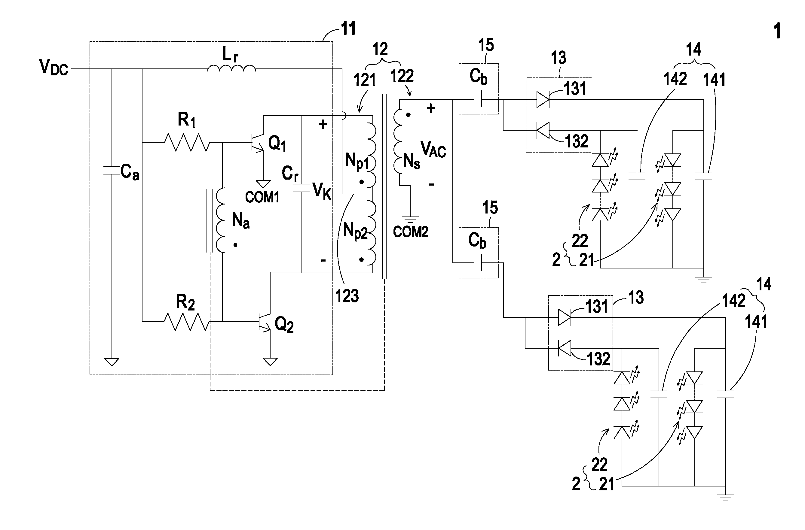
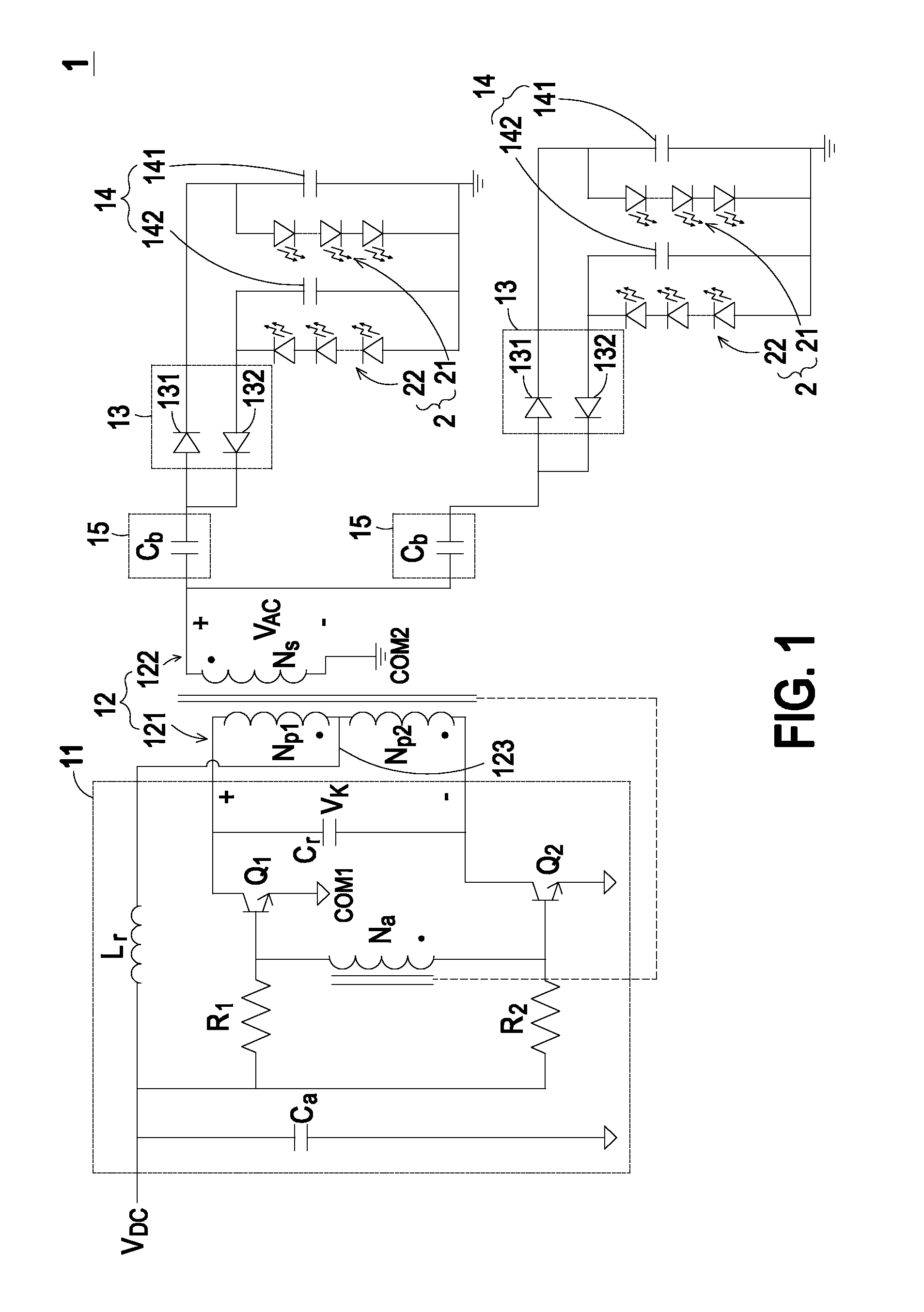
[0014]FIG. 1 is schematic circuit diagram illustrating a backlight driving circuit for use in a LCD panel according to the present invention. The backlight driving circuit 1 is applied to a LCD panel for driving plural LED strings 2. As shown in FIG. 1, the backlight driving circuit 1 comprises a self-excited oscillation circuit 11, a transformer 12, a rectifying circuit 13, a filtering circuit 14 and a current-sharing circuit 15. An example of the self-excited oscillation circuit 11 includes but is not limited to a Royer converter. The self-excited oscillation circuit 11 receives a DC voltage VDC. According to the DC voltage VDC, the self-excited oscillation circuit 11 generates an oscillation voltage Vk to a primary side 121 of the transformer 12.

[0015]Please refer to FIG. 1 again. The self-excited oscillation circuit 11 comprises an inductor Lr, a first capacitor Ca, a second capacitor Cr, a first resistor R1, a second resistor R2, a first switch element Q1 and a second switch el...

second embodiment

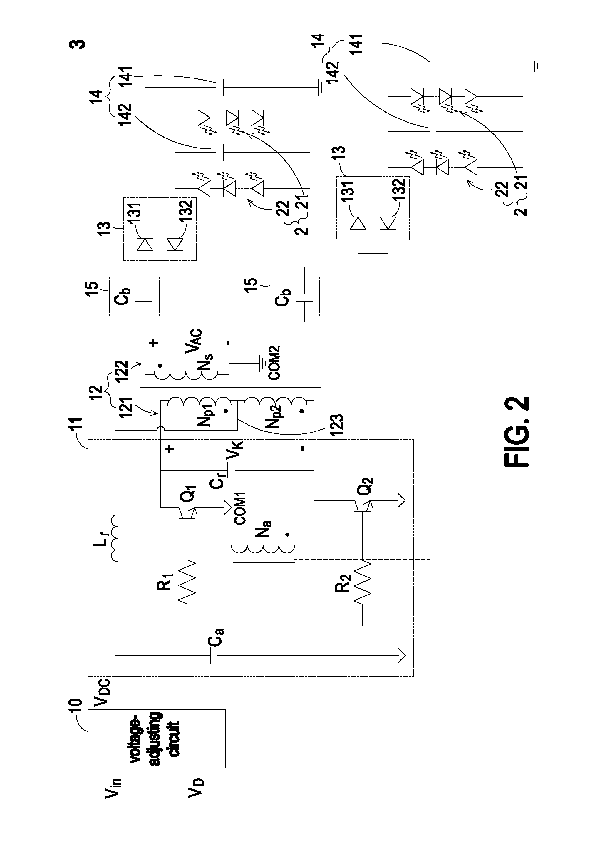
[0022]FIG. 2 is schematic circuit diagram illustrating a backlight driving circuit for use in a LCD panel according to the present invention. As shown in FIG. 2, the backlight driving circuit 3 comprises a self-excited oscillation circuit 11, a transformer 12, a rectifying circuit 13, a filtering circuit 14, a current-sharing circuit 15 and a voltage-adjusting circuit 10. The configurations and operating principles of the self-excited oscillation circuit 11, the transformer 12, the rectifying circuit 13, the filtering circuit 14 and the current-sharing circuit 15 are similar to those illustrated in FIG. 1, and are not redundantly described herein. The voltage-adjusting circuit 10 receives an input voltage Vin and a dimming signal VD. The dimming signal VD is transmitted from a system circuit board. According to a dimming signal VD, the magnitude or on phase of the DC voltage VDC is adjusted by the voltage-adjusting circuit 10. In addition, according to a dimming signal VD, the input...


PUM


Abstract

A backlight driving circuit includes a voltage-regulating circuit, a self-excited oscillation circuit, a transformer, a rectifying circuit and a filtering circuit. The voltage-regulating circuit is used for receiving an input voltage and adjusting the input voltage into a DC voltage. The self-excited oscillation circuit generates an oscillation voltage according to the DC voltage. The transformer includes a first primary winding assembly and a secondary winding assembly. The first primary winding assembly is connected with the self-excited oscillation circuit for receiving the oscillation voltage, so that the secondary winding assembly is induced to generate an AC output voltage. The rectifying circuit is used for rectifying the AC output voltage into a DC driving voltage. The filtering circuit is connected to the rectifying circuit and plural LED strings for filtering the DC driving voltage, so that the plural LED strings are driven by the filtered DC driving voltage.

Description

FIELD OF THE INVENTION[0001]The present invention relates to a backlight driving circuit, and more particularly to a backlight driving circuit for use in a LCD panel.BACKGROUND OF THE INVENTION[0002]Nowadays, LCD televisions have experienced great growth and are now rapidly gaining in popularity. As known, backlight modules are crucial components of LCD panels. In general, cold cathode fluorescent lamps (CCFLs) and light emitting diodes (LEDs) have been widely used as light sources of the backlight modules. Since a cold cathode fluorescent lamp uses a mercury gas, it is prone to environmental pollution. With maturity of the LED technology, LED gradually replaces CCFL as the backlight source of the LCD television. In comparison with CCFL, LED has reduced volume and power consumption. That is, the use of LED is effective for facilitating miniaturization of the LCD panel, achieving better color saturation and meeting the environmentally-friendly requirement.[0003]Generally, the LCD pan...

Claims


Application Information

Patent Timeline
IPC IPC(8): H05B37/02
CPCH05B33/0815H05B45/39H05B45/375H05B45/382
Inventor CHANG, SHIH-HSIENHUANG, YAO-TIEN
Owner DELTA ELECTRONICS INC
Learn More