Dead-time compensation apparatus of pwm inverter and method thereof

a technology of inverter and dead-time compensation, which is applied in the direction of motor/generator/converter stopper, dynamo-electric converter control, polyphase induction motor starter, etc., can solve the problems of low-frequency harmonic components, significant output voltage error of inverter, and reduction of fundamental components of output voltage of inverter

Active Publication Date: 2011-06-30
DELTA ELECTRONICS INC
View PDF2 Cites 22 Cited by
  • Summary
  • Abstract
  • Description
  • Claims
  • Application Information

AI Technical Summary

Benefits of technology

[0012]In order to solve the above-mention problems, a dead-time compensation apparatus of a PWM inverter is disclosed. The inverter has a plurality of switching elements, and turn-on and turn-off states of the switching elements are controlled by a gate driver circuit to drive an induction motor using a constant V / f control. Furthermore, a three-phase output current of the inverter is detected by a current detecting circuit to be as an analog detecting current. The dead-time compensation apparatus of a PWM inverter includes an analog-to-digital conversion unit, a voltage / frequency control unit, a dead-time compensation logical unit, and a PWM generating unit.

Problems solved by technology

When the induction motor is operated at low speed and light load condition, output voltage error of the inverter is significant due to the voltage drop of the switching elements.
However, the fundamental components of the output voltage of the inverter reduce and the low-frequency harmonic components increase when the dead-time is added.
Hence, the low-frequency harmonic components could significantly influence the motor to cause current distortion in the zero-crossing current region when the motor is operated at an open-loop low-speed condition.
However, the ideal compensation voltage is not easily obtained due to the non-smoothing trapezoid compensation curve.
More particularly, the distortion of output current could cause a discontinuous motion of the induction motor when the induction motor is operated at low speed and light load condition.
However, a main disadvantage of this approach is that the voltage detecting circuit 60A increases hardware costs.

Method used


Image

  • Dead-time compensation apparatus of pwm inverter and method thereof
  • Dead-time compensation apparatus of pwm inverter and method thereof
  • Dead-time compensation apparatus of pwm inverter and method thereof

Examples


Embodiment Construction

[0026]Reference will now be made to the drawing figures to describe the present invention in detail.

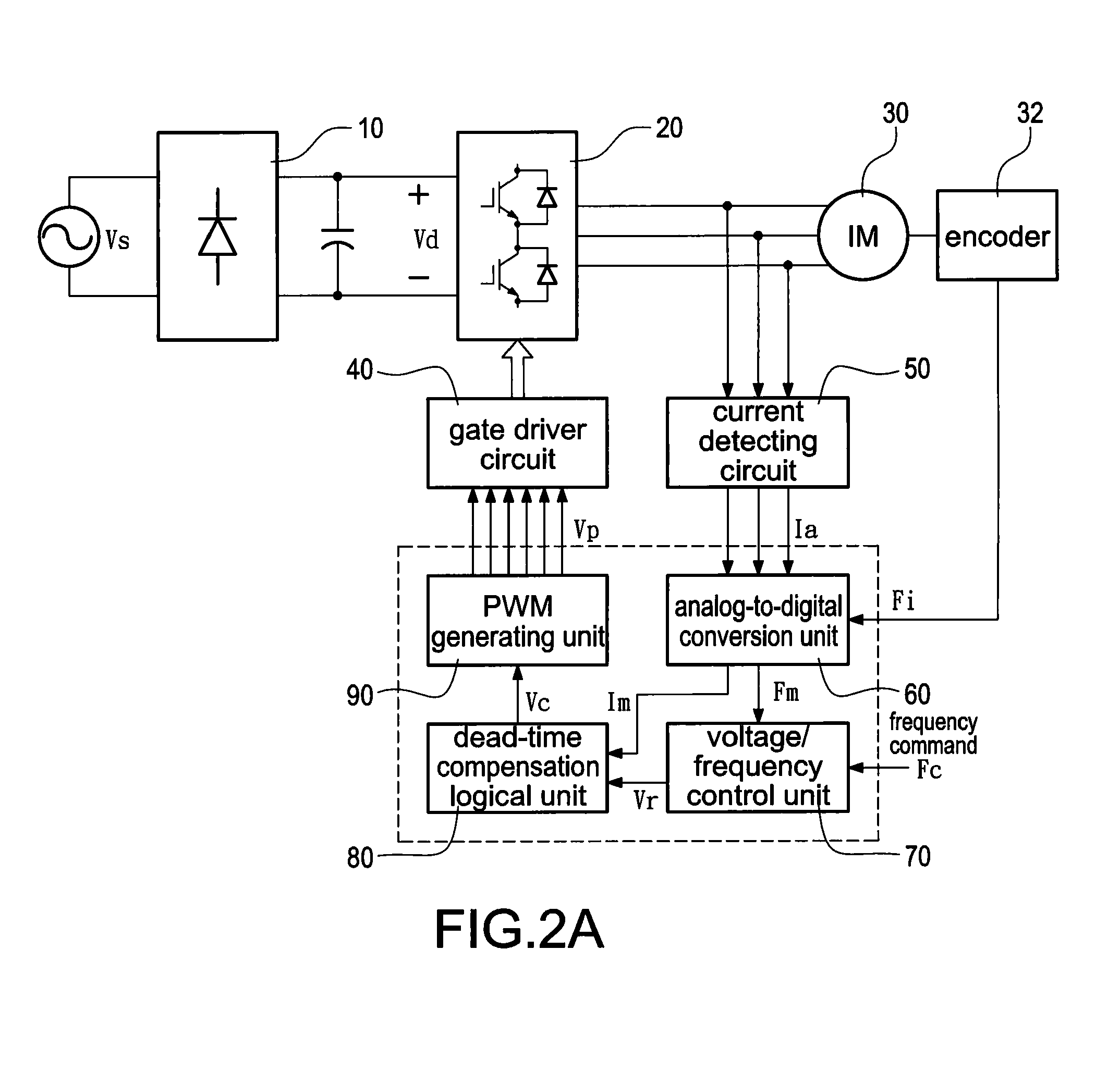
[0027]Reference is made to FIG. 2A which is a block diagram of a motor drive system operating in a closed-loop speed control. A rectifier 10 which is composed of a plurality of diodes (not labeled) is electrically connected to a three-phase AC source Vs. The AC voltage Vs is converted to a DC voltage. Afterward, a capacitor (not labeled) is added behind the rectifier 10 to reduce voltage ripple of the DC voltage to produce a smoothed DC voltage Vd. Finally, an inverter 20 converts the DC voltage Vd into a pulsating voltage to control an induction motor 30. Namely, the inverter 20 can invert the fixed-voltage and fixed-frequency AC source Vs into the variable-frequency and variable-voltage AC source to drive the induction motor 30.

[0028]Although the three-phase current and voltage are disclosed for demonstration in the present invention, a transformation is known as the abc-dq coordina...


PUM


Abstract

A dead-time compensation method is applied to a PWM inverter, which is provided to drive an induction motor using a constant V/f control. The method first calculates a root-mean-square current of the output instantaneous current of the inverter. Afterward, a lookup table of the root-mean-square current is used to obtain a dead-time compensation base voltage and a dead-time compensation per-unit voltage. Finally, the dead-time compensation base voltage is multiplied by the dead-time compensation per-unit voltage to produce a dead-time compensation voltage of the PWM inverter. Accordingly, the method reduces complexity of converting the current to the voltage to reach a faster real-time response. Furthermore, a more accurate dead-time compensation voltage is obtained without increasing hardware costs and the efficiency of operating the induction motor is improved at low speed and light load condition.

Description

BACKGROUND OF THE INVENTION[0001]1. Field of the Invention[0002]The present invention relates to a dead-time compensation apparatus of a PWM inverter and method thereof, and more particularly to a dead-time compensation apparatus of a PWM inverter and method thereof that produces a dead-time compensation voltage by using a lookup table.[0003]2. Description of Prior Art[0004]The commonly used technologies of controlling the inverter can be divided into two parts: scalar control and vector control. Although the scalar control is inferior at dynamic response, speed control ratio, and control accuracy in comparison with the vector control, the scalar control is simple in structure, easy to implement, and stable to control. Hence, the scalar control is widely used in a non-servo control system. The scalar control is also called a constant V / f control, or a variable voltage variable frequency control (VVVF control) method. Generally speaking, the constant V / f control is an open-loop contr...

Claims


Application Information

Patent Timeline
Patent Type & Authority Applications(United States)
IPC IPC(8): H02P27/04
CPCH02P27/047H02P2207/01H02P27/08
Inventor CHENG, LUNG-JAYHSIEH, TING-CHUNG
Owner DELTA ELECTRONICS INC
Why Eureka
Try Eureka