Battery fault detection apparatus

a fault detection and battery technology, applied in secondary cells, servicing/maintenance, safety/protection circuits, etc., can solve problems such as erroneous determination of monitoring state, overcharge of cells, and inability to determine whether the monitoring state is possible, so as to prevent making an erroneous determination

Active Publication Date: 2011-06-30
DENSO CORP
View PDF3 Cites 34 Cited by
  • Summary
  • Abstract
  • Description
  • Claims
  • Application Information

AI Technical Summary

Benefits of technology

[0016]According to the present invention, there is provided a battery fault determination apparatus configured to change between two different monitorin

Problems solved by technology

However, the above structure has a problem in that it is not possible to determine whether the monitoring state change between the fault diagnosis state and the overcharge detection state has been performed cor

Method used


Image

  • Battery fault detection apparatus
  • Battery fault detection apparatus
  • Battery fault detection apparatus

Examples


first embodiment

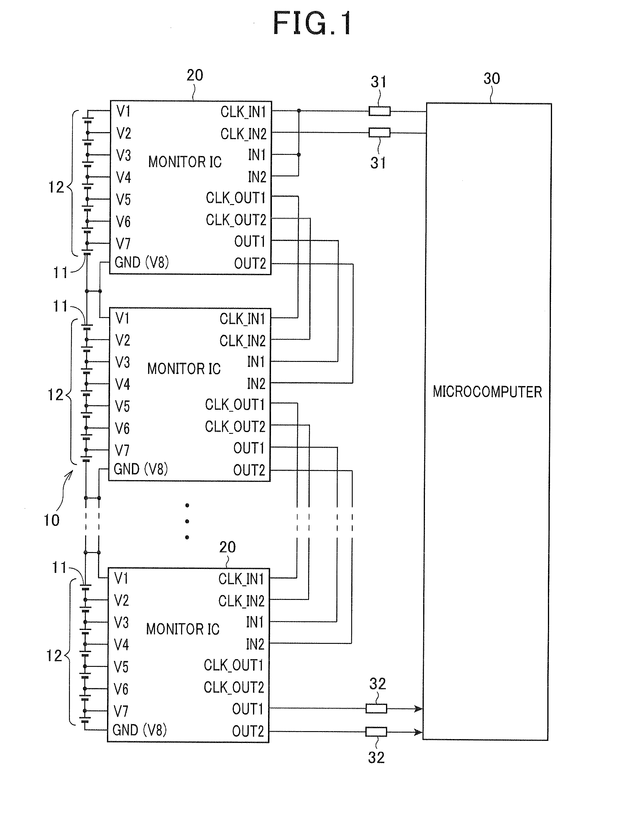
[0029]FIG. 1 is a diagram showing the overall structure of a battery control system including a battery fault detection apparatus according to a first embodiment of the invention. As shown in FIG. 1, the battery control system includes a battery pack 10, a plurality of monitor ICs 20 and a microcomputer 30.

[0030]The battery pack 10 includes a series connection of a predetermined number of unit batteries 12 each constituted of a predetermined number (7, for example) of rechargeable battery cells 11 connected in series. In this embodiment, a rechargeable lithium-ion battery is used as the battery cell 11.

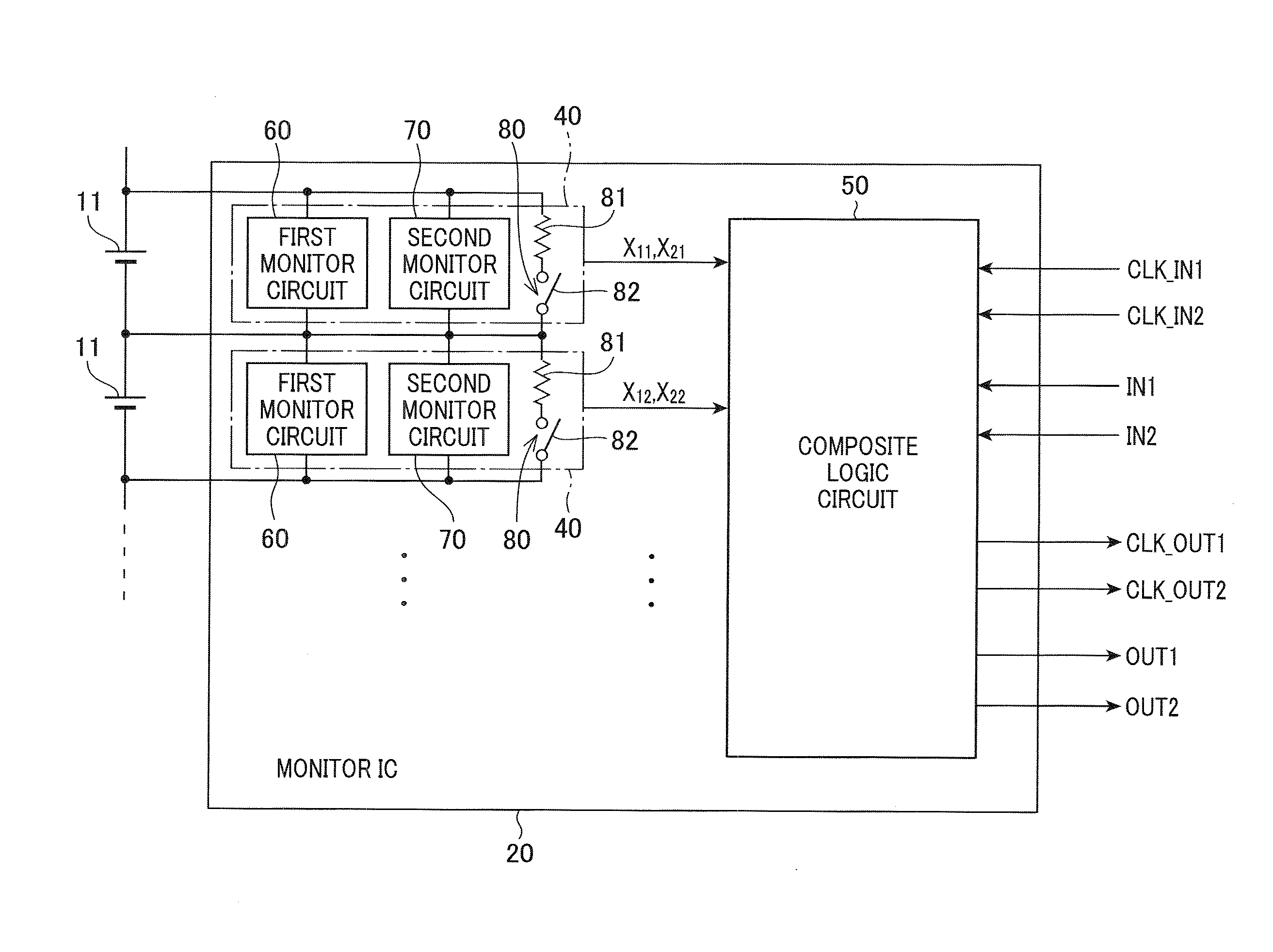
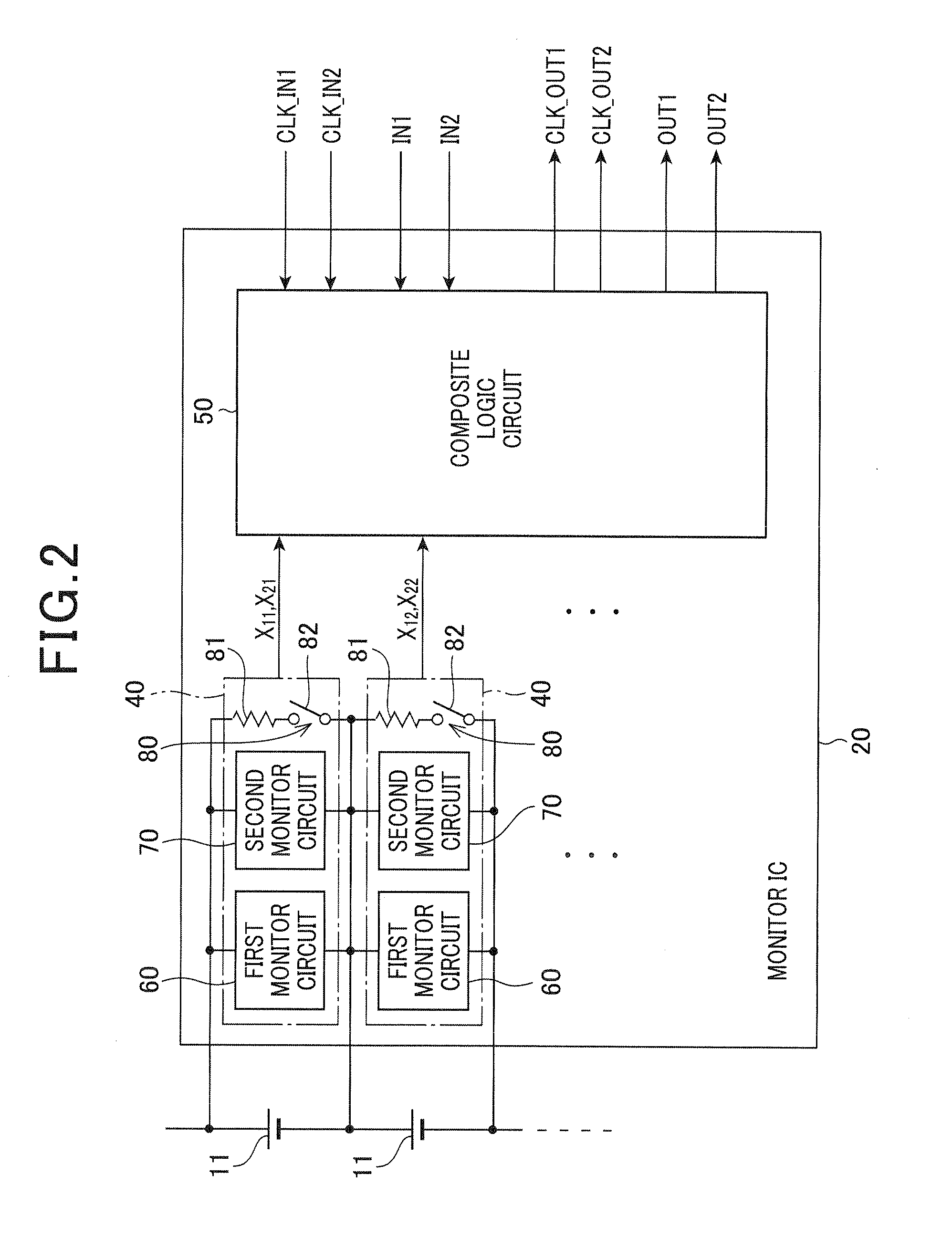
[0031]Each of the monitor ICs 20 has an overcharge / overdischarge detection function to detect overcharge and overdischarge of the battery cells 11, and a wire breakage detection function to detect breakage of wires directly or indirectly connected to the battery cells 11.

[0032]The overcharge / overdischarge detection function operates to monitor the battery cells 11 by comparing the vol...

second embodiment

[0097]Next, a second embodiment of the invention is described with emphasis on a difference with the first embodiment. In the above first embodiment, the state-transition fault detection section 51 is configured to detect a fault in the first clock signal, while in the second embodiment, the state-transition fault detection section 51 is configured to detect a fault in the second clock signal.

[0098]More specifically, in the second embodiment, the state-transition fault detection section 51 detects a case where the second clock signal is not received over a period in which the first clock signal has been received a predetermined number of times, and a case where the second clock signal remains at the same level although the first clock signal has been received a predetermined number of times after the second clock signal was received. In the following, there is provided an explanation of the operation of the state-transition fault detection section 51 to cause the pattern generation ...


PUM


Abstract

The battery fault determination apparatus includes battery monitor sections connected in a daisy chain, each of which is provided for a corresponding one of unit batteries each including battery cells connected in series to monitor the battery cells and output an output signal indicative of a monitoring result, and a control section configured to output a control signal to the battery monitor sections. The control signal and the output signal are cascaded through the battery monitor sections causing each battery monitor section to perform a state change between a state to monitor overcharge of the battery cells and a state to monitor wire breakage. Each battery monitor section is configured to receive the control signal from the immediately upstream-side battery monitor section, make a detection whether the state change has been performed correctly, and output the output signal including a detection result to the immediately downstream-side battery monitor section.

Description

[0001]This application claims priority to Japanese Patent Application No. 2009-292846 filed on Dec. 24, 2009, the entire contents of which are hereby incorporated by reference.BACKGROUND OF THE INVENTION[0002]1. Field of the Invention[0003]The present invention relates to a battery fault detection apparatus used to monitor a battery pack including battery cells connected in series.[0004]2. Description of Related Art[0005]There are proposed various structures to monitor battery cells for industrial use. For example, Japanese Unexamined Patent Application Publication (Translation of PCT Application) No. 2002-521792 discloses a structure to monitor the whole of industrial-use batteries by a battery centralized monitoring system constituted of a plurality of cell monitoring devices connected in a daisy chain.[0006]In this structure, the battery centralized monitoring system outputs a command to perform fault diagnosis to the cell monitoring devices in sequence, and diagnosis results by ...

Claims


Application Information

Patent Timeline
IPC IPC(8): G01N27/416G01R31/36H02J7/00H02J7/02
CPCG01R31/3658G01R31/026G01R31/396G01R31/54G01R31/3648H01M10/482G01R35/00H02J7/0047H01M10/4285H01M2010/4278H01M10/425H02J7/00302Y02E60/10
Inventor MIZOGUCHI, TOMOMICHISOBUE, SATOSHI
Owner DENSO CORP
Why Eureka
Try Eureka