Illumination device

Inactive Publication Date: 2011-06-30
SHARP KK
View PDF6 Cites 147 Cited by
  • Summary
  • Abstract
  • Description
  • Claims
  • Application Information

AI Technical Summary

Benefits of technology

[0027]Further, according to the present invention, in the illumination device configured as above, the light scattering material includes a fluid in which light scattering particles are dispersed and a transparent container for containing the fluid. With this configuration, the light scattering particles in the fluid may be swung with time utilizing the Brownian motion, which is effective in reducing coherence of the laser light with dynamic fluctuations.
[0028]Further, according to the present invention, in the illumination device configured as above, the transparent container is brought into close contact with the fluorescent substance. With this configuration, heat generated from the excited fluorescent substance as thermal energy is transferred through the transparent container to the fluid, to thereby facilitate the Brownian motion of the light scattering particles in the fluid.
[0029]Further, according to the present invention, the illumination device configured as above further includes a circulation path of the fluid, and a pump provided midway of the circulation path. With this configuration, the fluid circulating through th

Problems solved by technology

Also in such illumination device, light having high coherence may leak to the outside to lead to the alleged risk of harming the eye.
In the illumination device for exciting the fluorescent substance by irradiating the fluorescent substance by the laser light from the laser irradiation device to emit the visible light for

Method used


Image

  • Illumination device
  • Illumination device
  • Illumination device

Examples


first embodiment

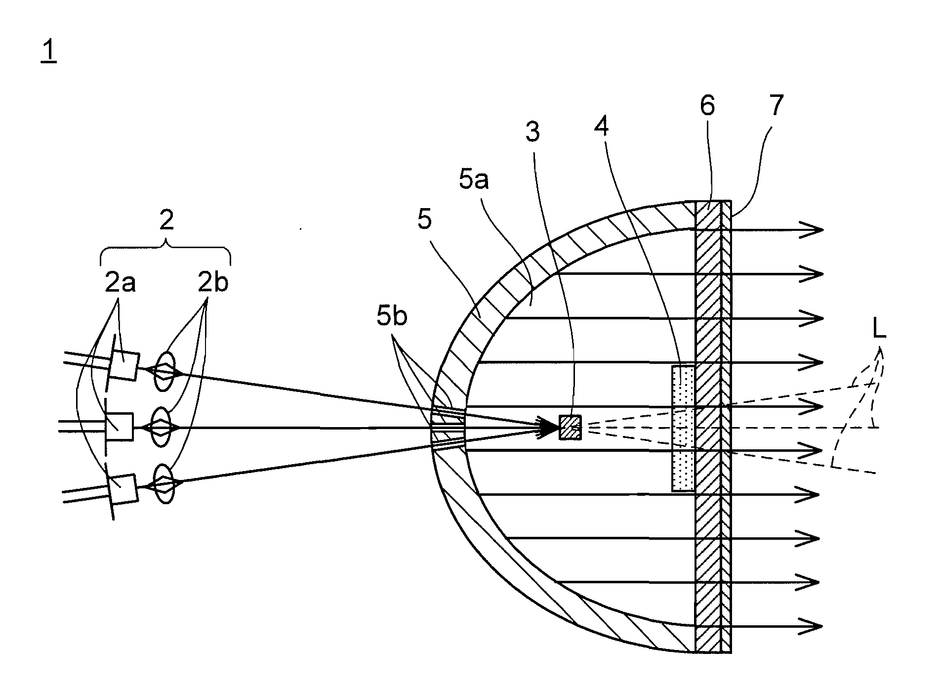
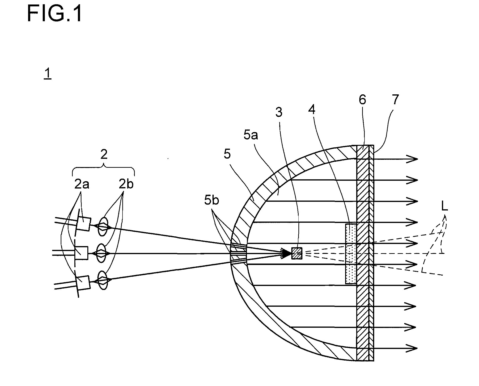
[0049]Referring to FIG. 1, a first embodiment of the present invention is described. FIG. 1 is a side cross-sectional view schematically illustrating structure of an illumination device according to the first embodiment.

[0050]As illustrated in FIG. 1, the illumination device according to the present invention which is denoted by 1 includes a laser irradiation device 2, a fluorescent substance 3 irradiated with laser light from the laser irradiation device 2, and a light scattering material 4 placed on and around an optical axis L of the laser light. The illumination device 1 excites the fluorescent substance 3 by the laser light to convert the laser light to visible light (for example, white light) for use as illumination light. The illumination device 1 is used, for example, as an automobile headlight.

[0051]A reflecting mirror 5 has a concave part 5a for reflecting the visible light converted by the fluorescent substance 3 forward (to the right of the page in FIG. 1) and is, for ex...

second embodiment

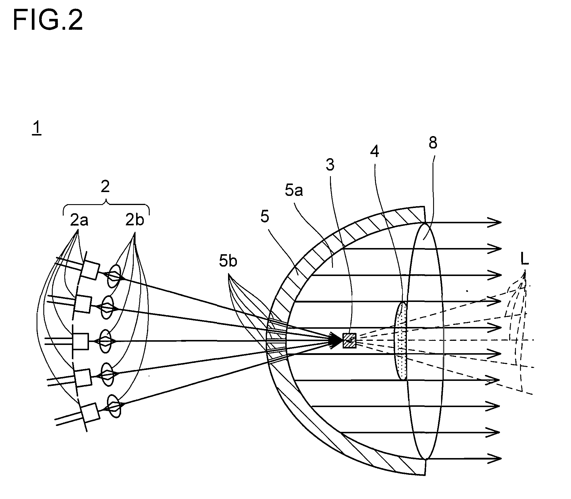
[0063]Next, referring to FIG. 2, a second embodiment of the present invention is described. FIG. 2 is a side cross-sectional view schematically illustrating structure of an illumination device according to the second embodiment. In the illumination device according to this embodiment, components similar to those of the illumination device according to the first embodiment illustrated in FIG. 1 are denoted by the same reference symbols, and their detailed descriptions are omitted.

[0064]The illumination device according to this embodiment which is denoted by 1 includes, instead of the cover 6 of the illumination device 1 of the first embodiment, a lens 8 inside the circumference at the front end of the reflecting mirror 5. The lens 8 has not only the function of controlling the solid angle of the fluorescent light to be projected but also the function of the cover for preventing dust or the like from entering the reflecting mirror 5. A convex lens is illustrated in FIG. 2 as an exampl...

third embodiment

[0073]Next, referring to FIGS. 3 and 4, a third embodiment of the present invention is described. FIG. 3 is a side cross-sectional view schematically illustrating structure of an illumination device according to the third embodiment, and FIG. 4 is a perspective view illustrating a light scattering material used in the illumination device. In the illumination device according to this embodiment, components similar to those of the illumination device according to the first embodiment illustrated in FIG. 1 are denoted by the same reference symbols, and their detailed descriptions are omitted.

[0074]In this embodiment, the laser irradiation device 2 includes a plurality of (in this embodiment, three) semiconductor laser elements 2a for emitting laser light, a plurality of collimator lenses 2b provided in correspondence with the semiconductor laser elements 2a, for converting the laser light emitted from the semiconductor laser elements 2a into parallel rays, and a condenser lens 2c provi...


PUM


Abstract

Provided is an illumination device capable of reducing coherence of laser light emitted from a laser irradiation device to ensure safety to the eye at low cost. In the illumination device for exciting a fluorescent substance by irradiating the fluorescent substance with the laser light from the laser irradiation device to emit visible light for use as illumination light, a light scattering material is placed on and around an optical axis of the laser light.

Description

[0001]This application is based on Japanese Patent Application No. 2009-297279 filed on Dec. 28, 2009 and Japanese Patent Application No. 2010-193296 filed on Aug. 31, 2010, the contents of which are hereby incorporated by reference.BACKGROUND OF THE INVENTION[0002]1. Field of the Invention[0003]The present invention relates to an illumination device for exciting a fluorescent substance by irradiating the fluorescent substance with laser light from a laser irradiation device to emit visible light for use as illumination light.[0004]2. Description of Related Art[0005]Conventionally, there has been proposed a safety measure regarding a communication device that uses laser light to transmit and receive signals for avoiding the risk to the eye caused by light having high coherence emitted to the outside of the transmitter.[0006]Taking as an example an infrared communication module described in Japanese Patent Application Laid-open No. 2003-258353, in a light source device used for a tra...

Claims


Application Information

Patent Timeline
IPC IPC(8): F21V9/16G02B27/20
CPCF21K9/56F21S48/115F21V29/58F21Y2101/02F21V9/16F21K9/64F21Y2115/10F21S41/16F21V9/35F21V13/14F21S41/176
Inventor TAKAHASHI, KOJIKAWANISHI, HIDENORI
Owner SHARP KK
Why Eureka
Try Eureka