
Modular Energy Storage Device for a High Voltage Electrical Power System

Inactive Publication Date: 2011-06-30
ABB RES LTD
View PDF1 Cites 3 Cited by
  • Summary
  • Abstract
  • Description
  • Claims
  • Application Information

AI Technical Summary

Benefits of technology

[0013]An advantage with the modular energy storage device according to the invention is that by arranging the first and second conductor to pass through the containers in parallel, the distance between the conductors will be reduced leading to a reduced loop inductance and hence a reduced voltage spike will appear across the switch when the energy storage device is disconnected (see equation 2). As a result the rating of the disconnecting solid-state switch can be reduced. A further advantage is a minimised need for snubber circuits and varistors, the ratings of which at least can be significantly decreased. Additional advantages are that the energy storage device is compact, modular and has a flexible design.
[0015]In an embodiment of the invention, at least one of the conductors comprises an insulated cable. An advantage with the use of an insulated cable is that electrical insulation of the conductor is automatically achieved. Hence the conductors can be placed with a very short distance to each other or even surface to surface in order to minimise the loop inductance of the energy storage device. Additionally, the insulation between the conductor and the container will be improved. A further advantage is that the degree of safety increases since the cable insulation prevents a person from having accidental contact with the conductor.
[0016]In an embodiment of the invention both conductors comprise an insulated cable. An advantage with the use of insulated cables is that electrical insulation of the conductors is automatically achieved. Hence the conductors can be placed with a very short distance to each other or even surface to surface in order to minimise the loop inductance of the energy storage device. Moreover, the insulation between the conductors and the container will be improved. An additional advantage is that less isolation is required when both the conductors comprise an isolated cable.
[0017]In an embodiment of the invention the first conductor comprises a metal tube, in the following denoted tube, surrounding the second conductor. For example, the second conductor is a cable. An advantage with this embodiment is that the loop inductance will be even smaller compared with parallel conductors. Accordingly, the snubber circuit ratings, the varistor ratings and the solid-state switch ratings can be further reduced. This embodiment also minimises the risk of module short-circuits due to the fact that the second conductor is enclosed by the first conductor. This solution also provides for an easy installation procedure where a standard insulated high voltage cable easily can be pushed through the tube to form the return path of the current.
[0018]In an embodiment of the invention the second conductor comprises a second tube arranged with the envelope surface at a distance from the tube of the first conductor such that an electrical isolation is achieved between the tubes. One advantage with this embodiment is that the copper utilization is minimised.

Problems solved by technology

However, the availability of dc circuit breakers is limited and the ratings of these breakers are considerably low and less than the required voltage ratings in high voltage electrical power systems.
However, high voltage power applications require large electric bus bar constructions that inevitably lead to high loop inductance.
This voltage spike will have fatal effects and destroy the switches.
Such additional equipment is however costly.

Method used


Image

  • Modular Energy Storage Device for a High Voltage Electrical Power System
  • Modular Energy Storage Device for a High Voltage Electrical Power System
  • Modular Energy Storage Device for a High Voltage Electrical Power System

Examples


first embodiment

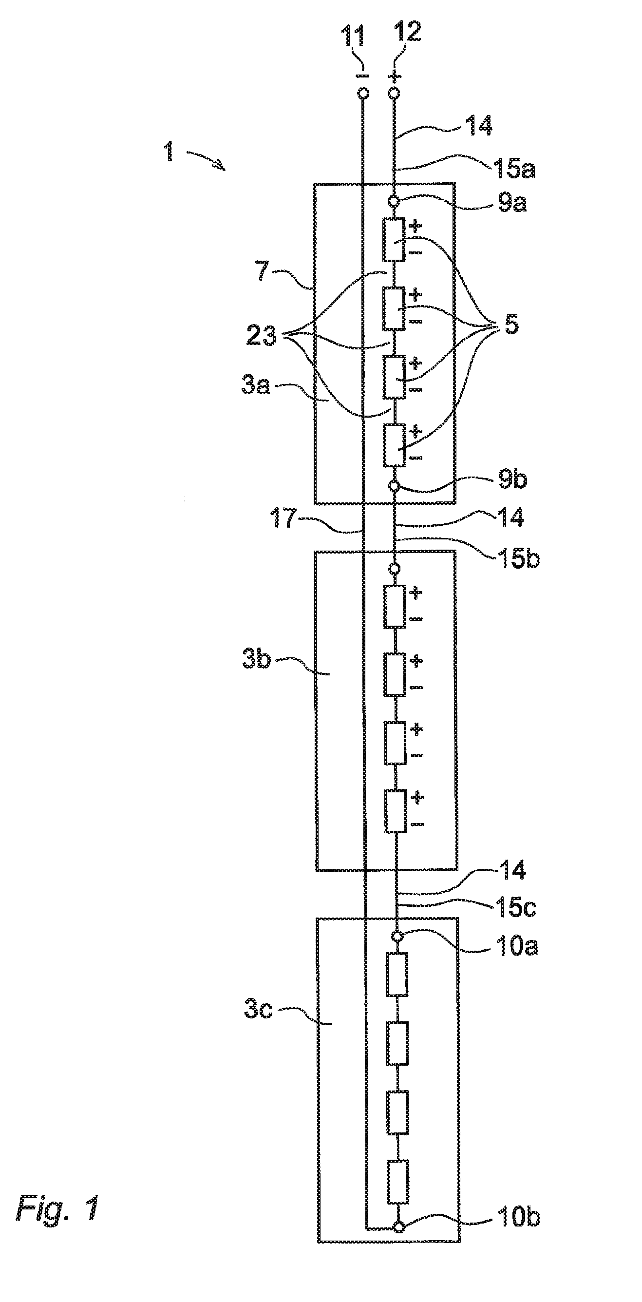
[0026]FIG. 1 shows a modular energy storage device 1 for a high voltage electrical power system according to the invention. High voltage electrical power systems can be networks for transmission or distribution of electrical energy as well as industries, hospitals and such. The same reference numerals are used throughout the figures for same or corresponding parts. The modular energy storage device includes two or more modules connected in series. The storage device 1 shown in FIG. 1 has three modules 3a-c. However, the number of module can be less or more than three. Each module 3a-c includes at least one dc power-source unit 5 enclosed in a container 7 and a positive 9a 10a and a negative 9b 10b terminal. The number of dc power-source units may vary. The device 1 further includes a positive 12 and a negative 11 pole, a first conductor 14 in the form of an insulated cable including a plurality of insulated cable parts 15a-c connected to the terminals 9a-b 10a-b of the modules 3a-c ...

second embodiment

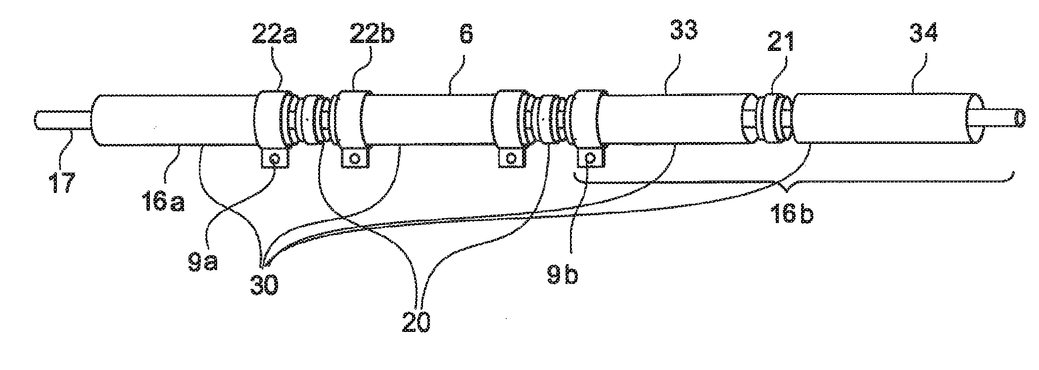
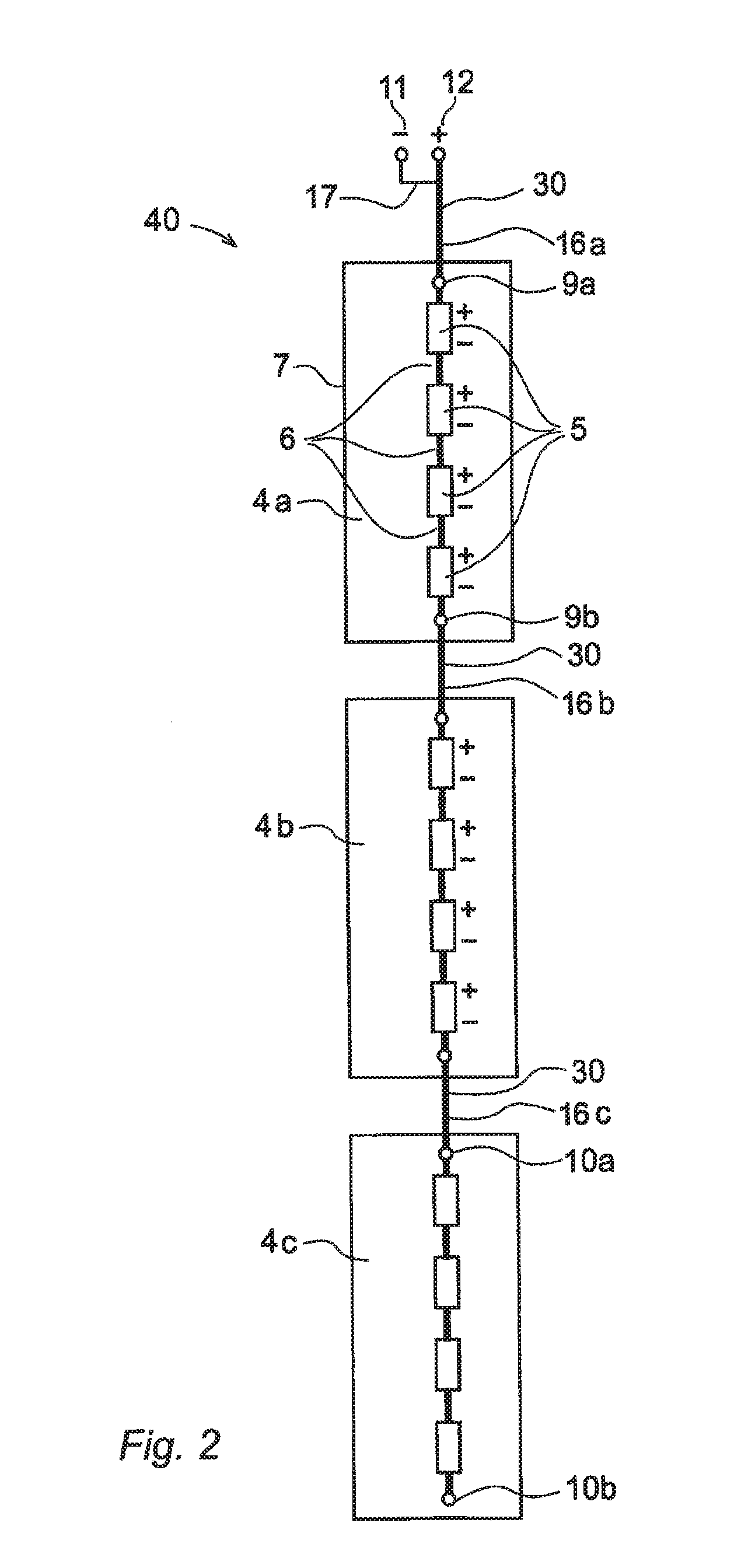
[0027]FIG. 2 shows a modular energy storage device 40 for a high voltage electrical power system according to the invention. The storage device 40 includes a first conductor 30 in the form of a conducting tube 30 which comprises a plurality of tube parts 16a-c connected to the terminals 9a-b 10a-b of the modules 4a-c to provide a series connection of the modules 4a-c, and a second conductor 17 connected to the negative terminal 10b of the last module 4c in the series connection of modules 4a-c. Alternatively, the second conductor 17 can be connected to the positive terminal 9a of the first module 3a in the series connection of modules 4a-c. The second conductor 17 is enclosed in the first conductor 30. The first tube 30 further comprises a plurality of tube parts 6 which interconnects the series equipment devices such as switches (not shown) and the dc power source units 5 thereby closing a current path between the positive 12 and negative 11 pole through the first 30 and second con...


PUM


Abstract

Storage device for a high voltage electrical power including at least two modules connected in series, each module including at least one dc power-source in a container with positive and negative terminals. The device including positive and negative poles, first and second conductors arranged to form a current path between the poles, the first conductor including a plurality of conductor parts connected to the terminals of the modules to provide a series connection, a first module of the series being connected to one of the poles, and the second conductor is connected between a last module in the series and the other pole, wherein the conductors are arranged to pass through the containers in parallel such that a current flows through the first conductor in a first direction and through the second conductor in an opposite second direction.

Description

CROSS-REFERENCE TO RELATED APPLICATIONS[0001]The present application is a continuation of pending International patent application PCT / EP2009 / 068038 filed on Dec. 30, 2009, which designates the United States and the content of which is incorporated herein by reference.FIELD OF THE INVENTION[0002]The present invention relates to a modular energy storage device for a high voltage electrical power system comprising at least one dc power-source unit enclosed in a container. By a high voltage electrical power system should be understood an electrical system within the range of 3 kV and upwards, preferably in the range of 10 kV and upwards. By energy storage device should be understood dc power source members connected in series to be within the range of 3 kV and upwards. One or more energy storage devices connected in parallel can for example be connected to the electrical power system via a power apparatus capable of controlling reactive power and / or active power. Examples of power appa...

Claims


Application Information

Patent Timeline
IPC IPC(8): H01M2/24H01M50/529H01M50/50H01M50/503H01M50/51H01M50/522
CPCH01M2/20H01M2/206H01M6/42H01M8/0247Y02B90/14H01M2250/10Y02E60/50H02J7/00H01M8/2465Y02B90/10H01M50/50H01M50/522H01M50/51H01M50/503H02M1/32
Inventor LARSSON, TOMASTINGLOW, FREDRIKDEMETRIADES, GEORGIOSHERMANSSON, WILLYPAPASTERGIOU, KONSTANTINOS
Owner ABB RES LTD
Features
  • Generate Ideas
  • Intellectual Property
  • Life Sciences
  • Materials
  • Tech Scout
  • Unparalleled Data Quality
  • Higher Quality Content
  • 60% Fewer Hallucinations
Learn More