Unitized overhead glazing systems

a technology of overhead glazing and unitized glazing, applied in the direction of ceilings, special buildings, climate sustainability, etc., can solve the problems of reducing the performance of shaded windows, and achieve the effect of reducing the heat island effect and more controlled lighting

Inactive Publication Date: 2011-07-07
ARCONIC INC
View PDF12 Cites 10 Cited by
  • Summary
  • Abstract
  • Description
  • Claims
  • Application Information

AI Technical Summary

Benefits of technology

A unitized overhead glazing system of the present disclosure finds use in numerous domestic and commercial applications, including, but not limited to, parking lot covers, car ports, caravan ports, bike ports, marina canopies, aircraft canopies, greenhouses, skylights, atriums, awnings, patio covers, play areas, classroom covers, barrel vault canopy, covered walkways, smoking canopies, school canopies, garden center canopies and the like. In an embodiment, a unitized overhead glazing system of the present disclosure finds use as an engineered solar photovoltaic canopy. In an embodiment, the solar photovoltaic canopy enables facility owners pursuing sustainable solutions to make use of the unobstructed and non-contested area above parking areas to, for example, generate electricity, provide shade, collect water, reduce heat island effect, provide more controlled lighting, and support infrastructure for plug-in vehicles. In an embodiment, the solar photovoltaic canopy qualifies for a significant number of Leadership in Energy and Environmental Design (LEED) points by virtue of the design and material selection of the canopy.

Problems solved by technology

The flush top surface also can prevent the glazing panels from being shaded by a traditional top mounted pressure plate and cover, and their performance reduced by the shade.

Method used


Image

  • Unitized overhead glazing systems
  • Unitized overhead glazing systems
  • Unitized overhead glazing systems

Examples


Embodiment Construction

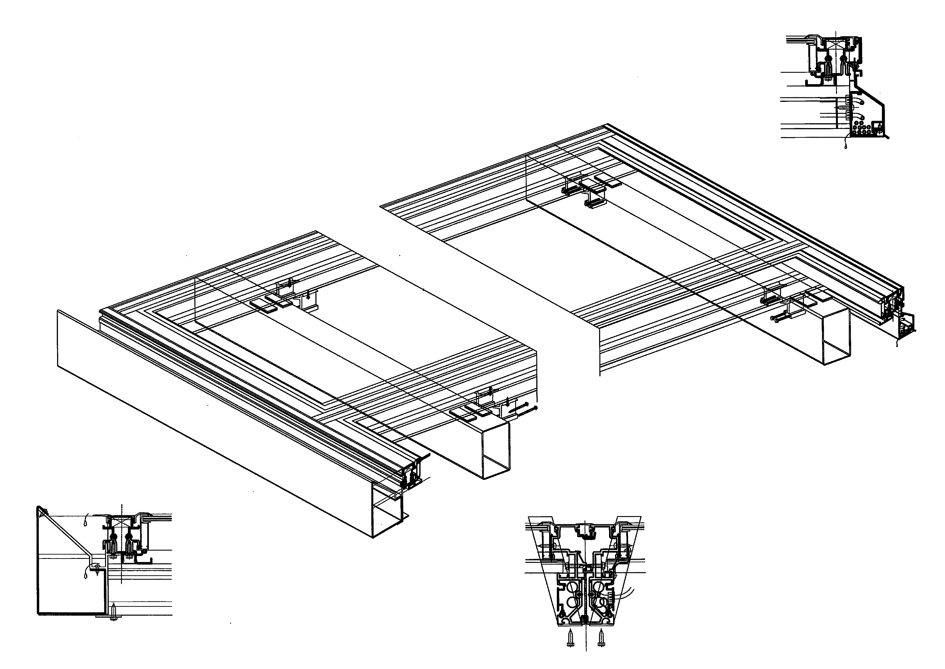
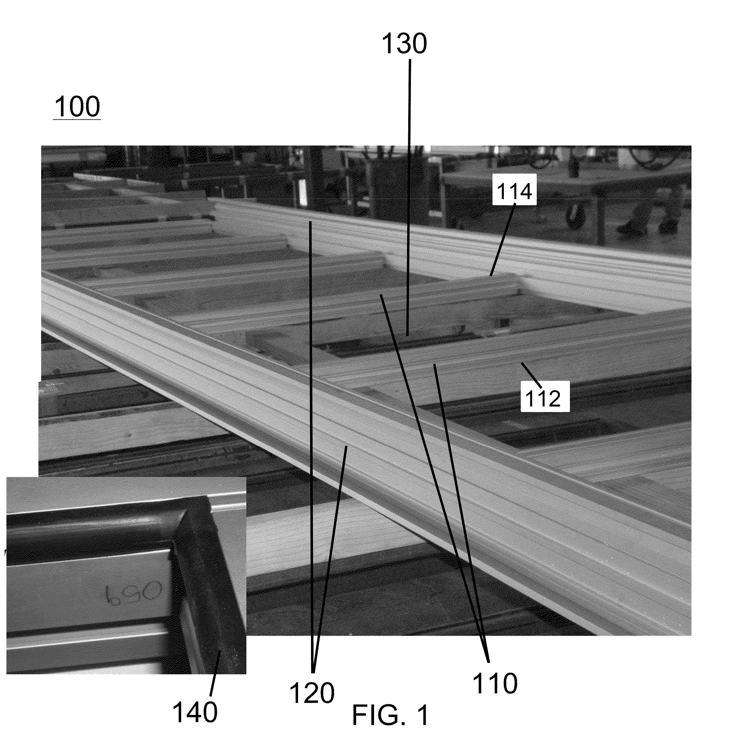
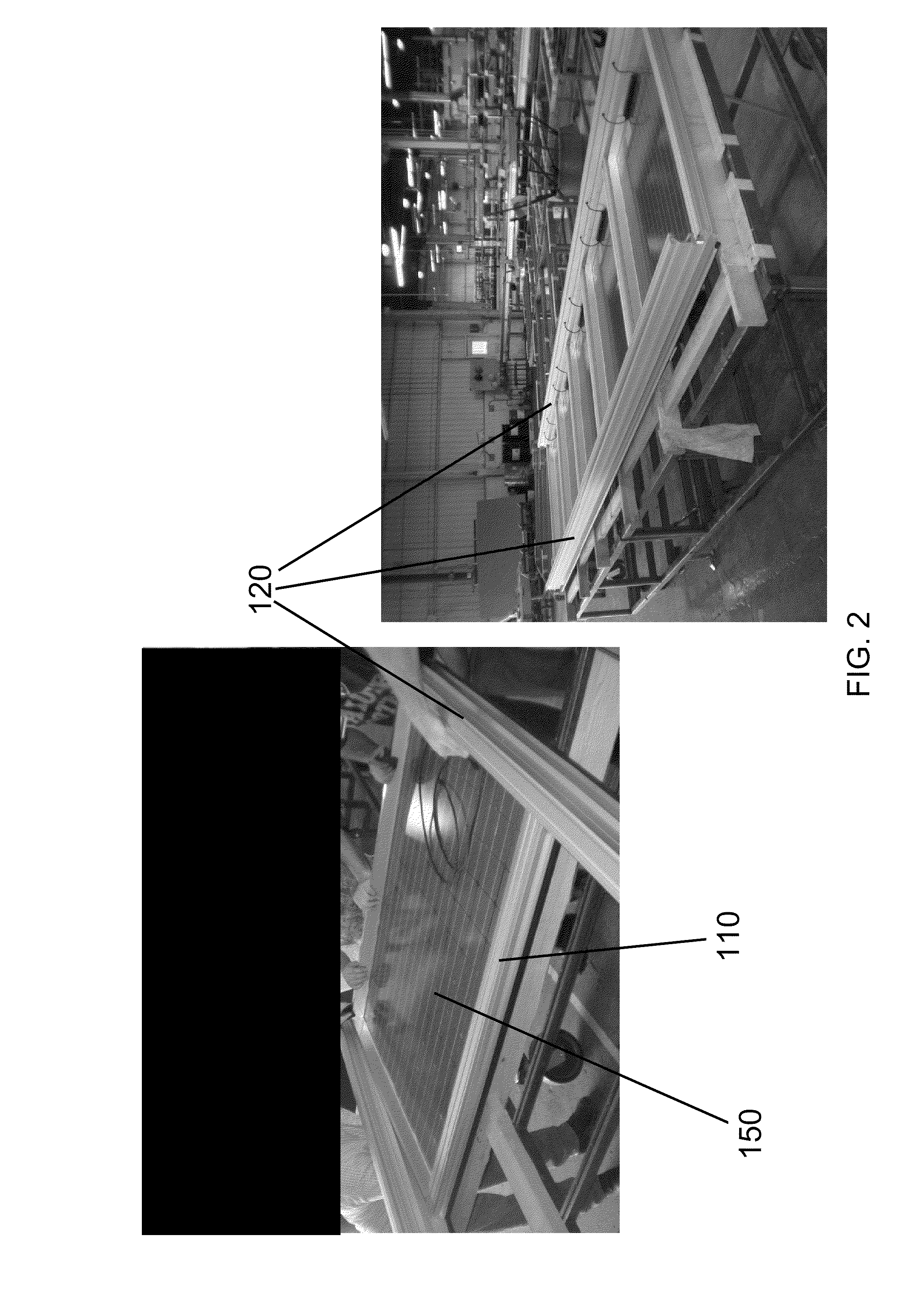
As used herein, the terms “glazing panel”, “panel” and “module” refer to a frame defining an opening and a panel having a top face and a back face fitted in the frame opening. The panel can be made of any building material, including, but not limited to, glass, plastic, aluminum, aluminum composite material, and solar (photovoltaic or PV) or combinations thereof. The panel may be single or multiple-glazed and may have any desired features, e.g. optical, strength, safety, solar energy control, or other properties, and may be transparent, translucent, opaque, colored, or tinted. In an embodiment, the panel is a Reynobond® Aluminum Composite Material (ACM) panel. In an embodiment, the panel is a solar panel.

As used herein, the term “structural framing cassette” refers to a plurality of horizontal framing members (“purlins”) interconnected with two vertical framing members “rafters”, to provide a plurality of glazing openings for holding glazing panels. In an embodiment, each structural...


PUM

PropertyMeasurementUnit
clearance heightaaaaaaaaaa
heightaaaaaaaaaa
heightaaaaaaaaaa

Abstract

In an embodiment, a unitized overhead glazing system of the present invention includes an array of assembled structural framing cassettes each having at least five photovoltaic modules. In an embodiment, each cassette forms one electrical string and is pre-wired, tested, and shipped ready to install for a variety of applications, including, but not limited to, parking canopies, covered walkways and specialty awnings. The unitized overhead glazing system can be utilized to generate electricity, provide shade, collect water, reduce heat island effect, provide more controlled lighting and support infrastructure for plug-in vehicles. The unitized overhead glazing system is designed to be installed and maintained from below, eliminating safety concerns associated with conventional canopies where work must be performed while on top of the canopy. The unitized overhead glazing system incorporates sealing methods and components to manage water, limit debris build up, and maximize energy yield.

Description

BACKGROUNDConventional overhead glazing systems for walkways, canopies, and the like, generally include a plurality of horizontal framing members or purlins and vertical framing members or rafters interconnected to form a structural framing unit and a top mounted pressure plate for retaining glazing panels in place against the framing unit. Typically, these conventional overhead glazing systems are assembled on-site, and the glazing panels are installed from above. Further, these conventional systems commonly utilize exterior fasteners, slots, sealing devices and holes for installing, maintaining and replacing panels.SUMMARYUnitized overhead glazing systems are disclosed herein.According to aspects illustrated herein, in an embodiment a unitized overhead glazing system of the present invention includes at least one assembled structural framing cassette, wherein the assembled structural framing cassette comprises a plurality of interconnected purlins and rafters forming a plurality o...

Claims


Application Information

Patent Timeline
Patent Type & Authority Applications(United States)
IPC IPC(8): E04C2/38B23P6/00
CPCE04D3/08Y10T29/49629E04F10/005E04H6/025F24J2/045F24J2/5207F24J2/5211F24J2002/5281Y02B10/20Y02E10/50Y02B10/12Y02E10/47H02S20/00H02S20/23H02S40/34E04D2003/0868H02S40/36F24S20/67F24S25/35F24S2025/014F24S25/20Y02B10/10
Inventor NAPORA, NICHOLAS A.VAN SON, VINCENT T.
Owner ARCONIC INC
Why Eureka
Try Eureka