Thermal foldback control for a light-emitting diode

a technology of light-emitting diodes and control circuits, applied in the direction of electric variable regulation, process and machine control, instruments, etc., can solve the problem of undesired flicker of leds

Active Publication Date: 2011-07-07
RICHTEK TECH
View PDF1 Cites 33 Cited by
  • Summary
  • Abstract
  • Description
  • Claims
  • Application Information

AI Technical Summary

Benefits of technology

Another object of the present invention is to provide a simple circuit and method that simultaneously monitor the temperature variations of an LED and its controller chip to adjust the driving current of the LED, thereby automatically regulating the temperatures of the LED and the controller chip.

Problems solved by technology

Therefore, the controller chip in the driver circuit is hard to dissipate its heat and sometimes becomes hotter than the LEDs, which will trigger the OTP mechanism to push the controller chip into a thermal protection mode, thereby turning off the driving current of the LEDs and causing the LEDs to undesirably flicker.

Method used


Image

  • Thermal foldback control for a light-emitting diode
  • Thermal foldback control for a light-emitting diode
  • Thermal foldback control for a light-emitting diode

Examples


Embodiment Construction

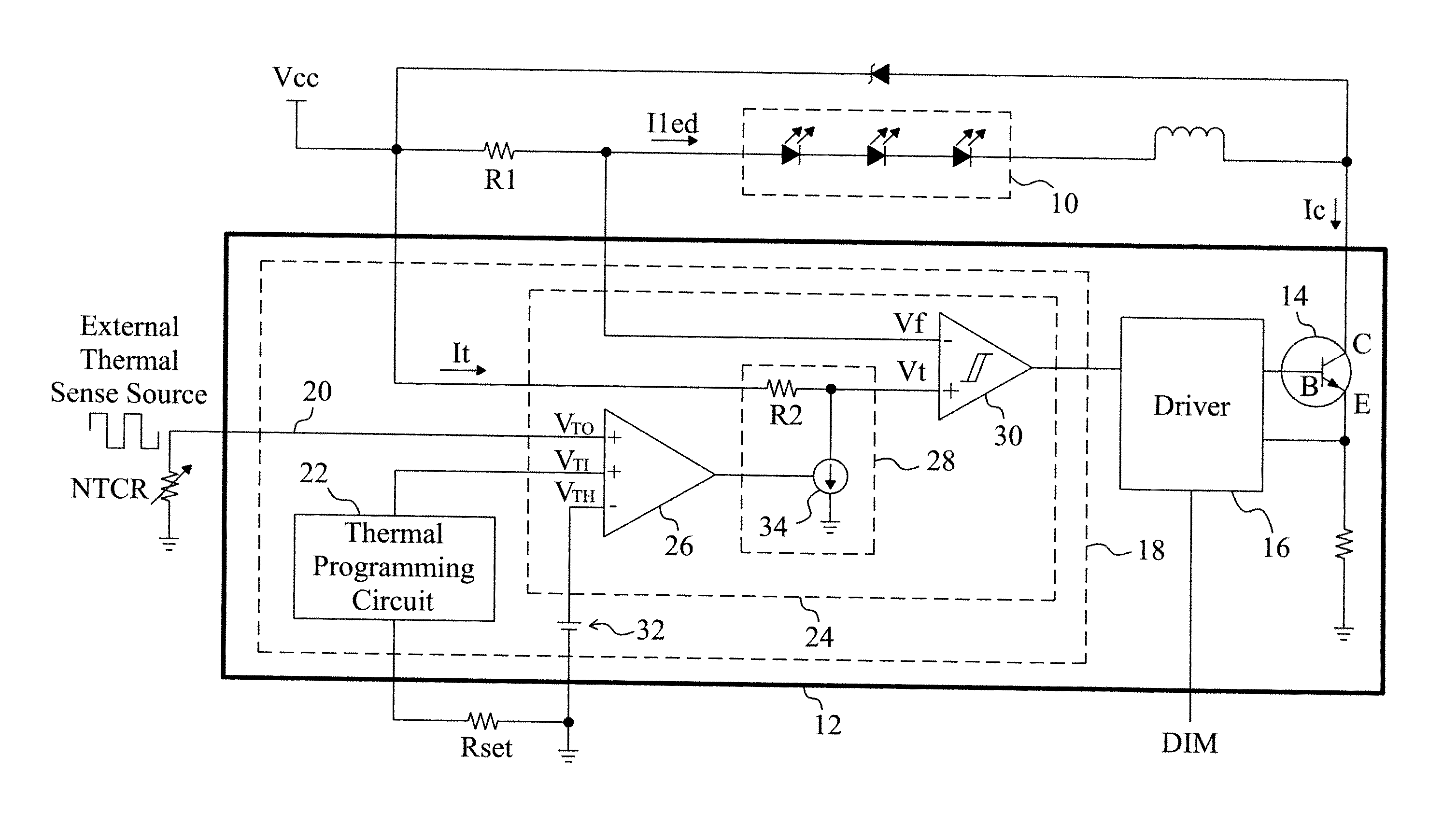
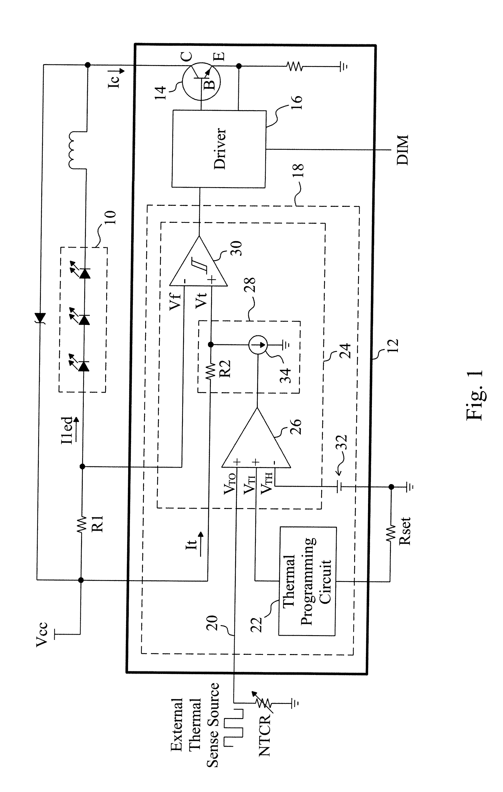
FIG. 1 is a circuit diagram of an embodiment according to the present invention, in which an LED array 10 is coupled with a power source Vcc through a resistor R1, and a controller chip 12 is coupled to the LED array 10 to control the driving current lied thereof. The controller chip 12 includes a bipolar junction transistor (BJT) 14 serially coupled to the LED array 10 to provide the collector current Ic as the driving current lied, and a driver 16 coupled to the base of the BJT 14 to control the collector current Ic. Similar to prior arts, the controller chip 12 has a dimming pin DIM coupled to the driver 16 to receive a dimming input for controlling the illumination of the LED array 10. The controller chip 12 further includes a thermal foldback control circuit 18 that provides a thermal regulation signal for the driver 16 to adjust the collector current Ic. A negative temperature coefficient resistor NTCR detects the temperature of the LED array 10 to generate an external thermal...


PUM


Abstract

By monitoring the temperature of an LED and the temperature of a controller chip for the LED, a thermal foldback control is employed to gradually decrease the driving current of the LED before the LED or the controller chip is over heated, so as to prevent an over temperature protection from being triggered to shutdown the controller chip to cause the LED to undesirably flicker.

Description

FIELD OF THE INVENTIONThe present invention is related generally to a light-emitting diode (LED) driver and, more particularly, to a thermal foldback control circuit and method for an LED.BACKGROUND OF THE INVENTIONThe controller chip for LED drivers is typically equipped with over temperature protection (OTP) which will shutdown the controller chip once the temperature of the controller chip increases over a setting value, to prevent the controller chip from being burnt out. The thermal foldback control is a protection mechanism for an LED, which will decrease the driving current of the LED when the temperature of the controller chip increases over a setting value, to avoid the temperature of the controller chip still increasing. The existing design of LED lamps concentrates on the security and heat dissipation of the LEDs, and thus puts the LEDs in a space with good air convection to reduce the surface temperature of the LEDs, while puts the driver circuit in another closed space....

Claims


Application Information

Patent Timeline
Patent Type & Authority Applications(United States)
IPC IPC(8): H05B37/02
CPCY02B20/341H05B33/0845H05B45/18Y02B20/30
Inventor HUANG, PEI-CHENGLIU, JING-MENG
Owner RICHTEK TECH
Why Eureka
Try Eureka