RF shimming with RF power regularization using a multi-channel RF transmit system for MRI

a multi-channel rf transmit system and rf power regularization technology, applied in the field of magnetic resonance arts, can solve the problems of inhomogeneity of radio frequency (rf) excitation, sometimes denoted as the bsub>1 /sub>field, and inability to achieve computationally efficient planning of magnetic resonance procedures, and achieve rapid rf shimming

Inactive Publication Date: 2011-07-07
KONINKLIJKE PHILIPS ELECTRONICS NV
View PDF1 Cites 13 Cited by
  • Summary
  • Abstract
  • Description
  • Claims
  • Application Information

AI Technical Summary

Benefits of technology

[0012]Another advantage resides in computationally efficient planning of a magnetic resonance procedure employing a multi-transmit RF system.

Problems solved by technology

Accordingly, for high field magnetic resonance scanners, such as scanners with a static (B0) magnetic field of about 3 Tesla or higher, the wavelength of magnetic resonance becomes sufficiently short that the homogeneity of the radio frequency (RF) excitation, sometimes denoted as the B1 field, can become problematically inhomogeneous over a volume of interest.
However, computation of the SAR is computationally intensive, and typically entails modeling RF power absorption using a model of the subject including accurate information regarding electromagnetic characteristics of the organs and tissues of the subject (for a human or other biological subject).
Such computationally intensive approaches are undesirable for practical applications such as diagnostic or clinical magnetic resonance imaging.

Method used


Image

  • RF shimming with RF power regularization using a multi-channel RF transmit system for MRI
  • RF shimming with RF power regularization using a multi-channel RF transmit system for MRI
  • RF shimming with RF power regularization using a multi-channel RF transmit system for MRI

Examples


Embodiment Construction

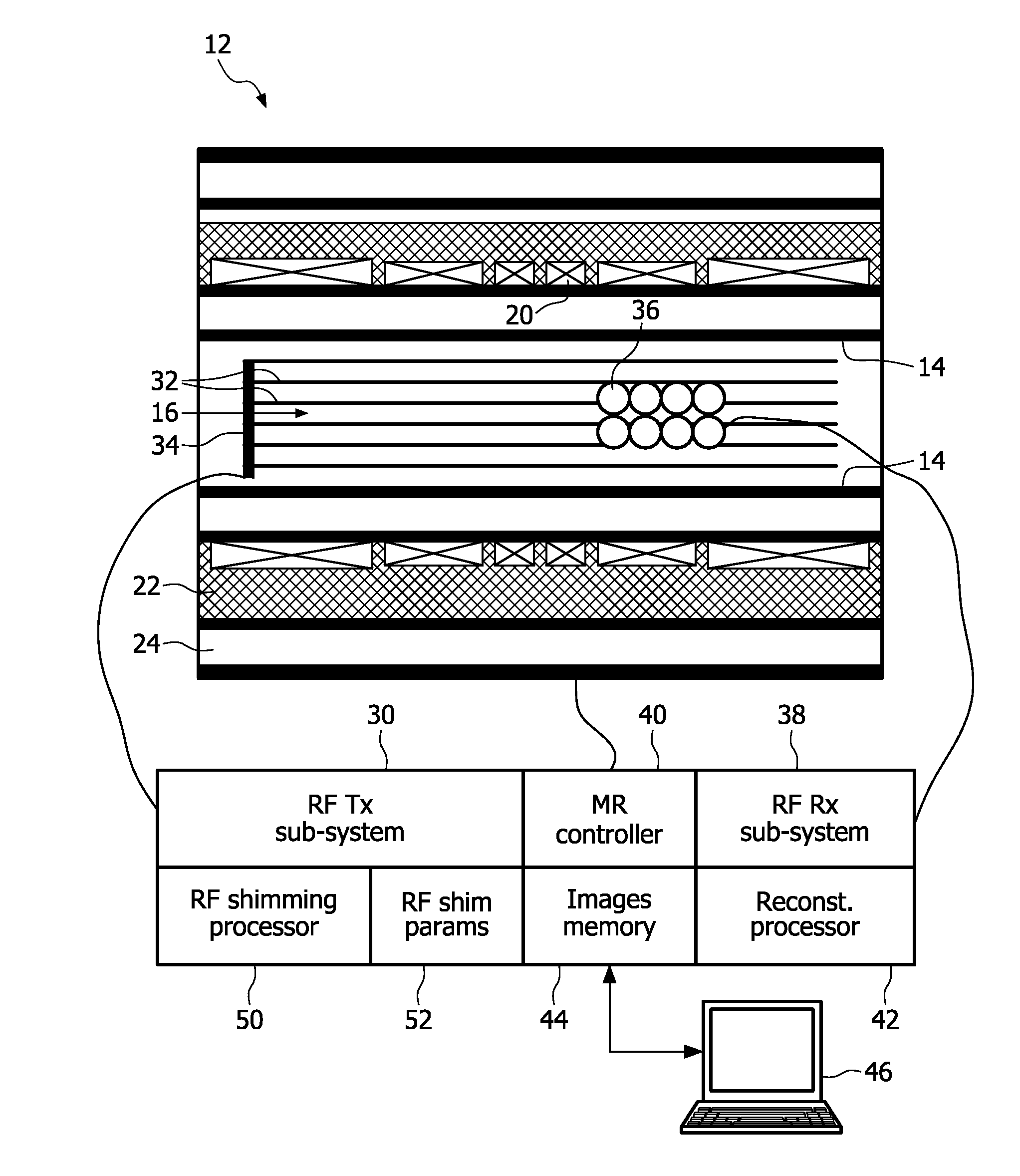
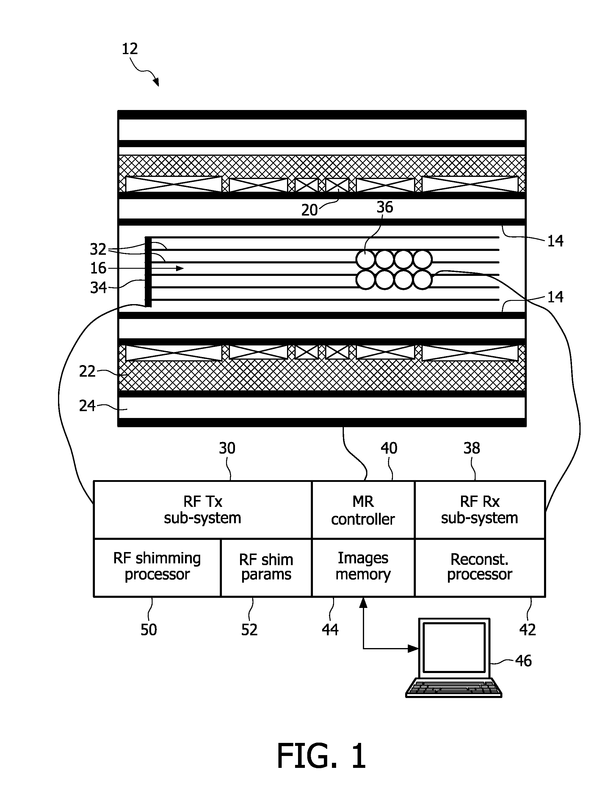
[0019]With reference to FIG. 1, an illustrative magnetic resonance (MR) system includes a magnetic resonance scanner 12 which in the illustrated embodiment is a horizontal-bore type system having an annular housing with an inner cylindrical wall 14 surrounding and defining a generally cylindrical horizontally-oriented bore 16. The illustrated horizontal-bore type system is an example; the disclosed methods and apparatuses are compatible with substantially any type of magnetic resonance system. The magnetic resonance system includes superconducting magnet windings 20 arranged to generate a static (B0) magnetic field oriented coaxially with the bore 16 at least in an examination region generally located at or near the center of the bore 16. For MR systems in which RF shimming is of interest, the static (B0) magnetic field is typically about 3 Tesla or higher, although RF shimming can also be of advantage in lower field MR systems. To keep the superconducting magnet windings 20 below a...


PUM


Abstract

A magnetic resonance system comprises: a magnetic resonance scanner (12) including a multi-channel RF transmit system (32, 34); an RF shimming processor (50) configured to compute complex amplitude values for operative channels of the multi-channel RF transmit system based on a figure-of-merit (70) comprising a weighted combination of a B1 uniformity measure and a total power measure; and an RF transmit sub-system (30) configured to drive the multi-channel RF transmit system to excite magnetic resonance using the complex amplitude values computed by the RF shimming processor for the operative channels of the multi-channel RF transmit system.

Description

FIELD OF THE INVENTION[0001]The following relates to the magnetic resonance arts, such as magnetic resonance imaging, magnetic resonance spectroscopy, and so forth.BACKGROUND OF THE INVENTION[0002]The magnetic resonance frequency scales with magnetic field. Accordingly, for high field magnetic resonance scanners, such as scanners with a static (B0) magnetic field of about 3 Tesla or higher, the wavelength of magnetic resonance becomes sufficiently short that the homogeneity of the radio frequency (RF) excitation, sometimes denoted as the B1 field, can become problematically inhomogeneous over a volume of interest.[0003]A solution to this problem is to use a multi-transmit system, in which a plurality of transmit coils are operated independently. The transmit elements can be arranged as independently operable conductors of a “whole body” RF coil, or as local coils disposed on or proximate to the subject. By adjusting or shimming the relative RF power outputs of the transmit elements,...

Claims


Application Information

Patent Timeline
Patent Type & Authority Applications(United States)
IPC IPC(8): G01R33/44
CPCG01R33/288G01R33/5659G01R33/5612G01R33/3415
Inventor KATSCHER, ULRICHGRAESSLIN, INGMAR
Owner KONINKLIJKE PHILIPS ELECTRONICS NV
Why Eureka
Try Eureka