

Biological signal measuring wearing device and wearable motion assisting apparatus
a wearable motion and signal technology, applied in the field of wearable motion assisting apparatuses and wearable signal measuring wearable devices, can solve the problems of difficult physical-challenged people or elderly people, easy movement for typical people, etc., and achieve the effect of facilitating the attachment of biological signal sensors
- Summary
- Abstract
- Description
- Claims
- Application Information
AI Technical Summary
Benefits of technology
Problems solved by technology
Method used
Image

Examples
first embodiment
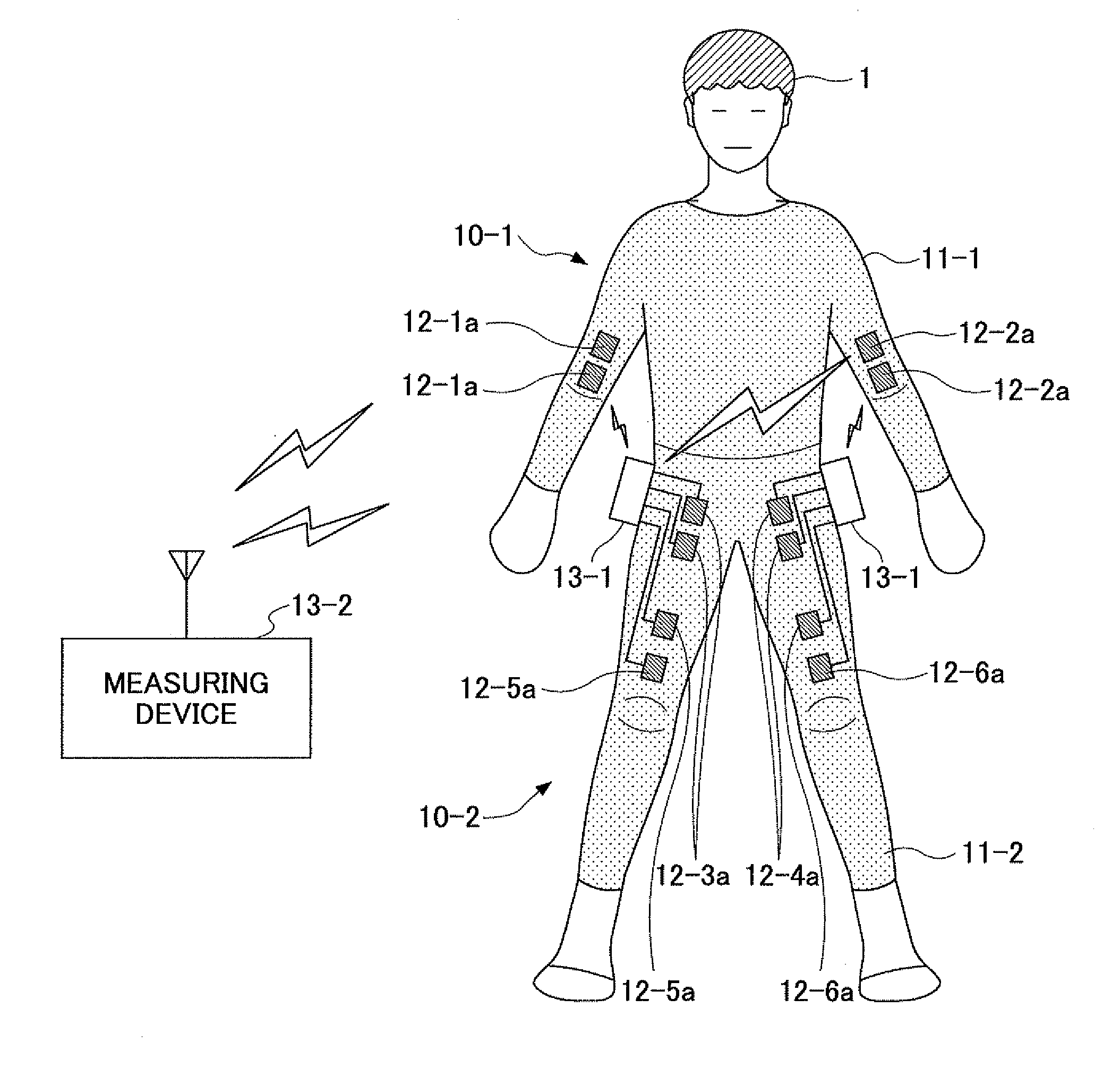
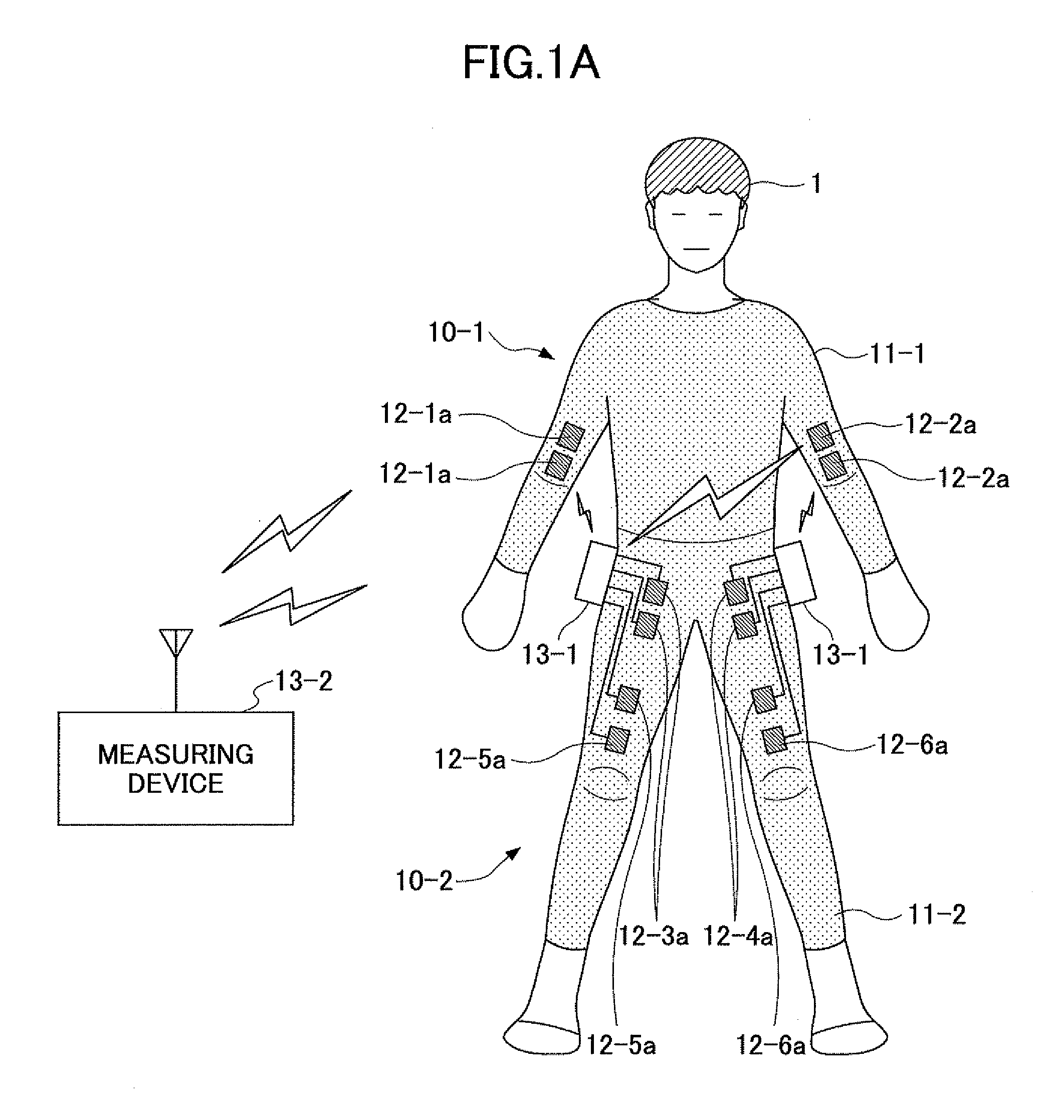
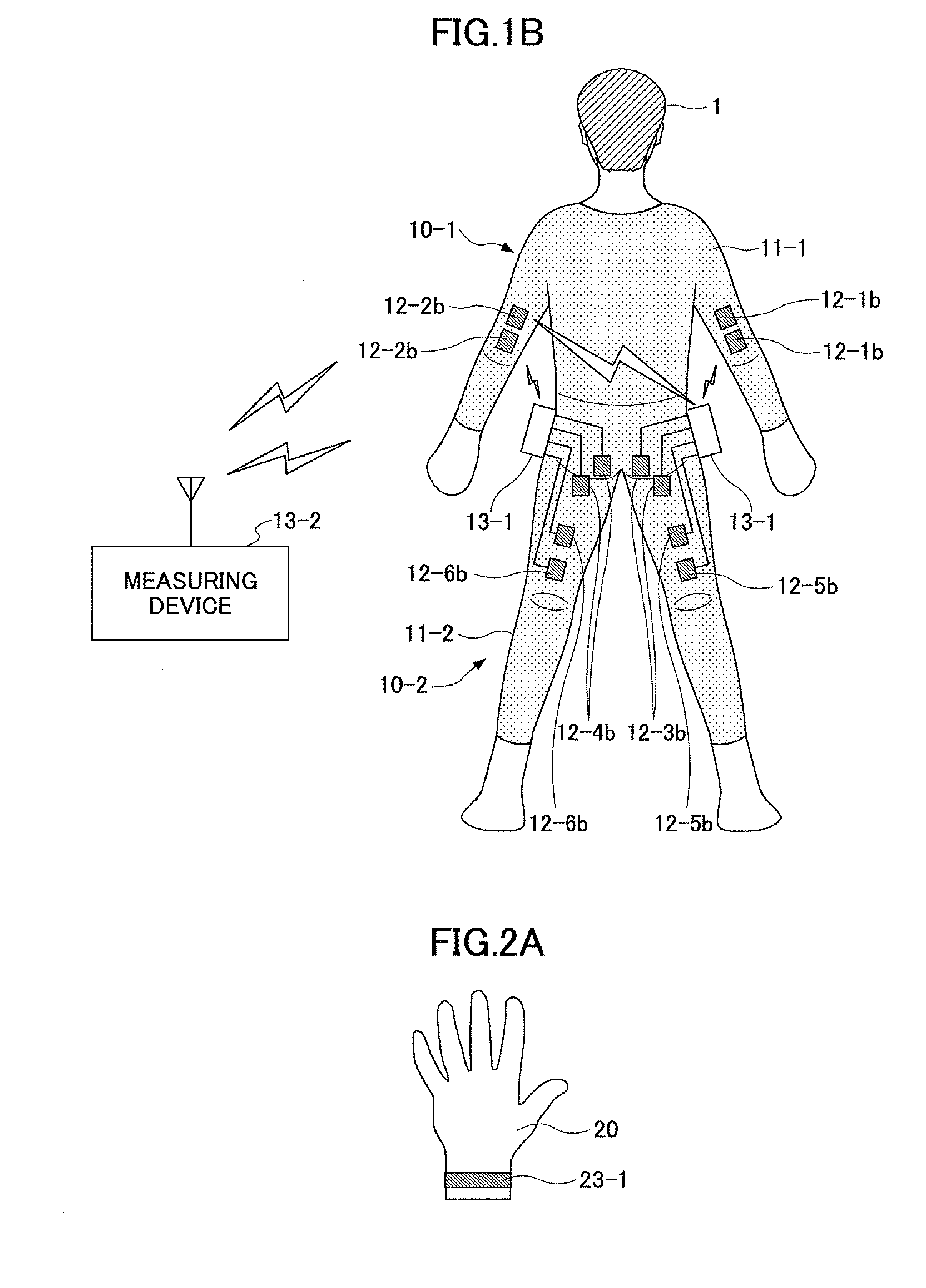
[0055]First, a description is given of a biological signal measuring wearing device where the present invention is implemented. FIG. 1A is a front view of the biological signal measuring wearing device in which the present invention is implemented. Further, FIG. 1B is a rear view of the biological signal measuring wearing device in which the present invention is implemented. The drawings shown in FIGS. 1A and 1B illustrate a case where a wearer 1 wears an upper-body biological signal measuring wearing device 10-1 and a lower-body biological signal measuring wearing device 10-2.
[0056]A biological signal measuring wearing device according to this embodiment includes a wearing device body configured to cover the body surface of a wearer and be put on the wearer, and has a biological signal sensor (an electrode part) configured to detect a bioelectric potential signal as a biological signal sensor at at least one position where a biological signal from the wearer is measureable on the i...
second embodiment
[0125][Application of Biological Signal Measuring Wearing Device to Wearable Motion Assisting Apparatus]
[0126]Next, as a second embodiment, a description is given, using drawings, of a case where the biological signals obtained from the above-described biological signal measuring wearing device are applied to a wearable motion assisting apparatus. In the following description, by way of example, a description is given of a hardware configuration and a drive control technique for providing more natural motions such as walking, standing, and sitting with HAL (Hybrid Assistive Limb), a wearable exoskeletal power-assisted system, in order to assist or reconstruct the lower-body motor function through biped walking.
[0127]A wearable motion assisting apparatus in this embodiment performs control using a surface electro myogram / myoelectricity (EMG), which is a command signal from the upper center generated in the form of a potential on the muscle surface via the spinal cord, and further, in...
third embodiment
[0147]Further, a description is given below, using FIG. 10 through FIG. 13B, of an embodiment other than the above-described embodiments as a third embodiment. FIG. 10 is a schematic diagram illustrating the exterior of a biological signal measuring wearing device having biological signal sensor groups on a lower-body (legs) wearing device body. FIG. 10 is a schematic diagram illustrating, as an example of this embodiment, the exterior of a biological signal measuring wearing device 100 having a lower-body (legs) wearing device body 101 provided with biological signal sensor groups (biological signal detecting part groups) 104a through 104f including multiple biological signal sensors 102 (biological signal detecting parts). Further, the biological signal measuring wearing device 100 of this embodiment has a symmetrical structure. Thus, a structure on the posterior side of the left leg is illustrated in the left half of the drawing, and a structure on the anterior side of the left l...
PUM
 Abstract
Description
Claims
Application Information