Measuring transducer of vibration-type

a technology of measuring transducers and vibration types, which is applied in the direction of instruments, specific gravity measurement, liquid/fluent solid measurement, etc., can solve the problems of unavoidable increase in the mass inability to anticipate the foreseeable future of mass production, and inability to obtain the structural integrity of the measuring transducer, so as to ensure the accuracy of measurement and the accuracy of measurement. , the effect of ensuring the accuracy of measuremen

Active Publication Date: 2011-07-14
ENDRESS HAUSER FLOWTEC AG
View PDF12 Cites 59 Cited by
  • Summary
  • Abstract
  • Description
  • Claims
  • Application Information

AI Technical Summary

Benefits of technology

[0052]An advantage of the invention is additionally, among other things, that, through the application of curved measuring tubes, lasting mechanical stresses, for example, as a result of thermally related expansion of the measuring tubes or as a result of clamping forces introduced into the measuring transducer because of the tube arrangement, are largely prevented within the tube arrangement or at least kept very low and, as a result, the accuracy of measurement, as well as also the structural integrity of the measuring transducer, are safely obtained, even in the case of extremely hot media, or in the case of temperature gradients strongly fluctuating within the tube arrangement as a function of time. Moreover, due to the symmetry characteristics of the tube arrangement, also those transverse forces caused by bending oscillations of curved measuring tubes can largely be neutralized, which—as discussed, among other things, in the initially mentioned EP-A 1 248 084 and U.S. Pat. No. 7,350,421—act essentially perpendicularly to the longitudinal section planes of the measuring transducer, or its tube arrangement and can be quite damaging for the accuracy of measurement of measuring transducers of vibration-type.
[0053]A further advantage of the measuring transducer of the invention resides additionally in the fact that predominantly established, structural designs, such as regards materials used, joining technology, manufacturing steps, etc., can be applied, or must only be slightly modified, whereby also manufacturing costs are, in total, quite comparable to those of conventional measuring transducers. As a result, a further advantage of the invention is to be found in the fact that, thereby, not only an opportunity is created for implementing comparatively compact measuring transducers of vibration-type also with large nominal diameters of over 150 mm, especially with a nominal diameter of larger 250 mm, with manageable geometric dimensions and empty dimensions, but, additionally, also, this can be accomplished in an economically sensible manner.
[0054]The measuring transducer of the invention is, consequently, especially suitable for measuring flowable media guided in a pipeline having a caliber of larger 150 mm, especially of 300 mm or greater. Additionally, the measuring transducer is also suitable for measuring also mass flows, which are, at least at times, greater than 1000 t / h, especially, at least at times, amounting to more than 1500 t / h, such as can occur e.g. in the case of applications for measuring petroleum, natural gas or other petrochemical materials.
[0055]The invention, as well as other advantageous embodiments thereof, will now be explained in greater detail on the basis of examples of embodiments presented in the figures of the drawing. Equal parts are provided in the figures with equal reference characters; when required to avoid clutter or when it otherwise appears sensible, already mentioned reference characters are omitted in subsequent figures. Other advantageous embodiments or further developments, especially also combinations of first only individually explained aspects of the invention, will become evident additionally from the figures of the drawing, as well as also alone from the dependent claims.

Problems solved by technology

Along with that, also the empty mass of the measuring transducer increases unavoidably, with conventional measuring transducers of large nominal diameter already having an empty mass of about 400 kg.
As a result, it can be said that industrial grade, mass producible, measuring transducers of conventional design and materials with nominal diameters far above 300 mm cannot be expected in the foreseeable future both for reasons of technical implementability, as well as also due to economic considerations.

Method used


Image

  • Measuring transducer of vibration-type
  • Measuring transducer of vibration-type
  • Measuring transducer of vibration-type

Examples


Embodiment Construction

[0063]While the invention is susceptible to various modifications and alternative forms, exemplary embodiments thereof have been shown by way of example in the drawings and will herein be described in detail. It should be understood, however, that there is no intent to limit the invention to the particular forms disclosed, but on the contrary, the intention is to cover all modifications, equivalents, and alternatives falling within the spirit and scope of the invention as defined by the intended claims.

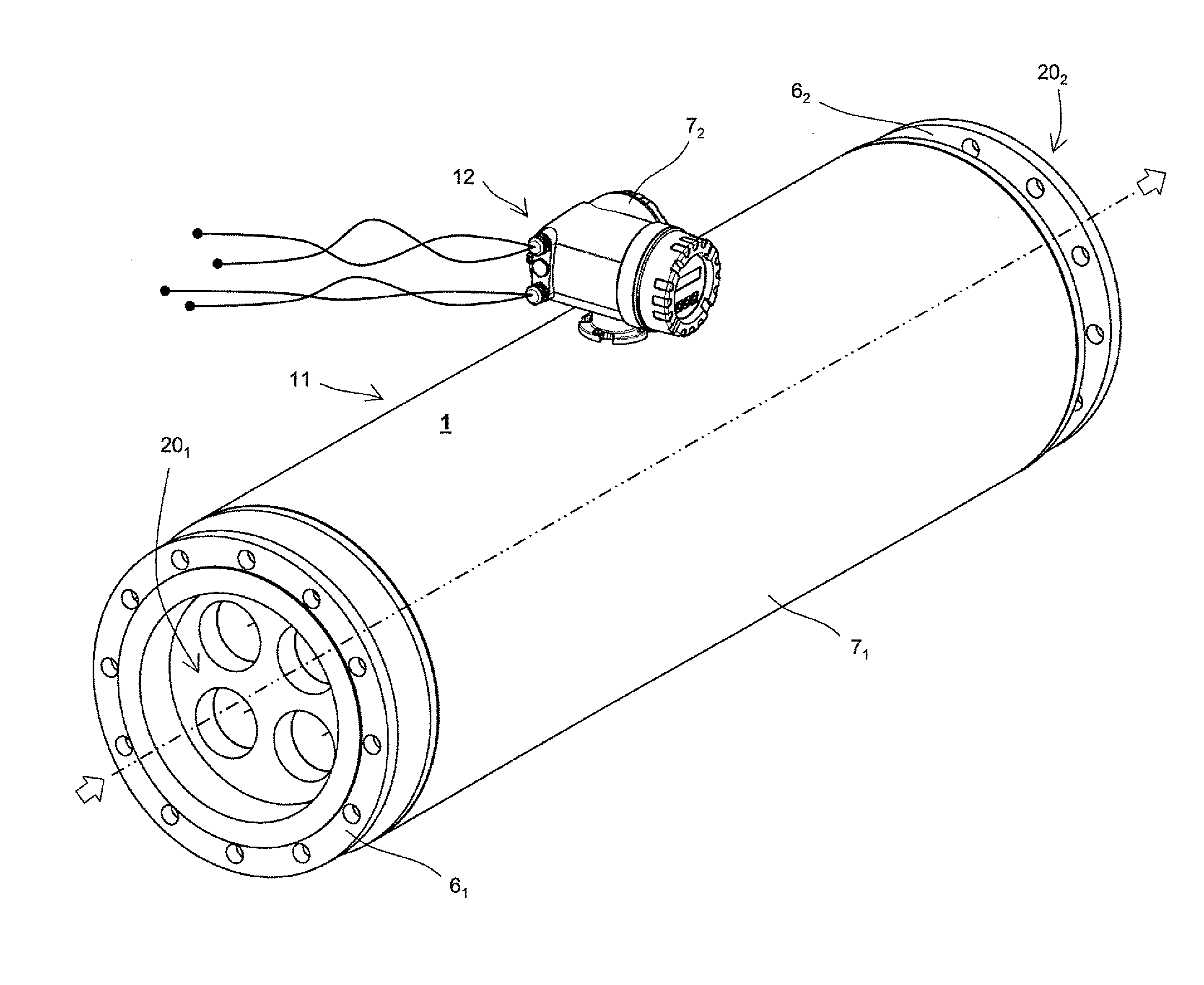
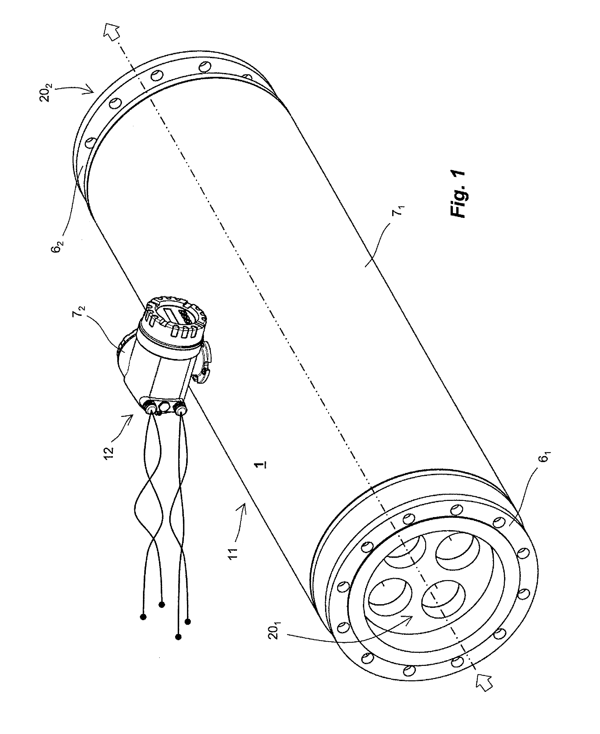
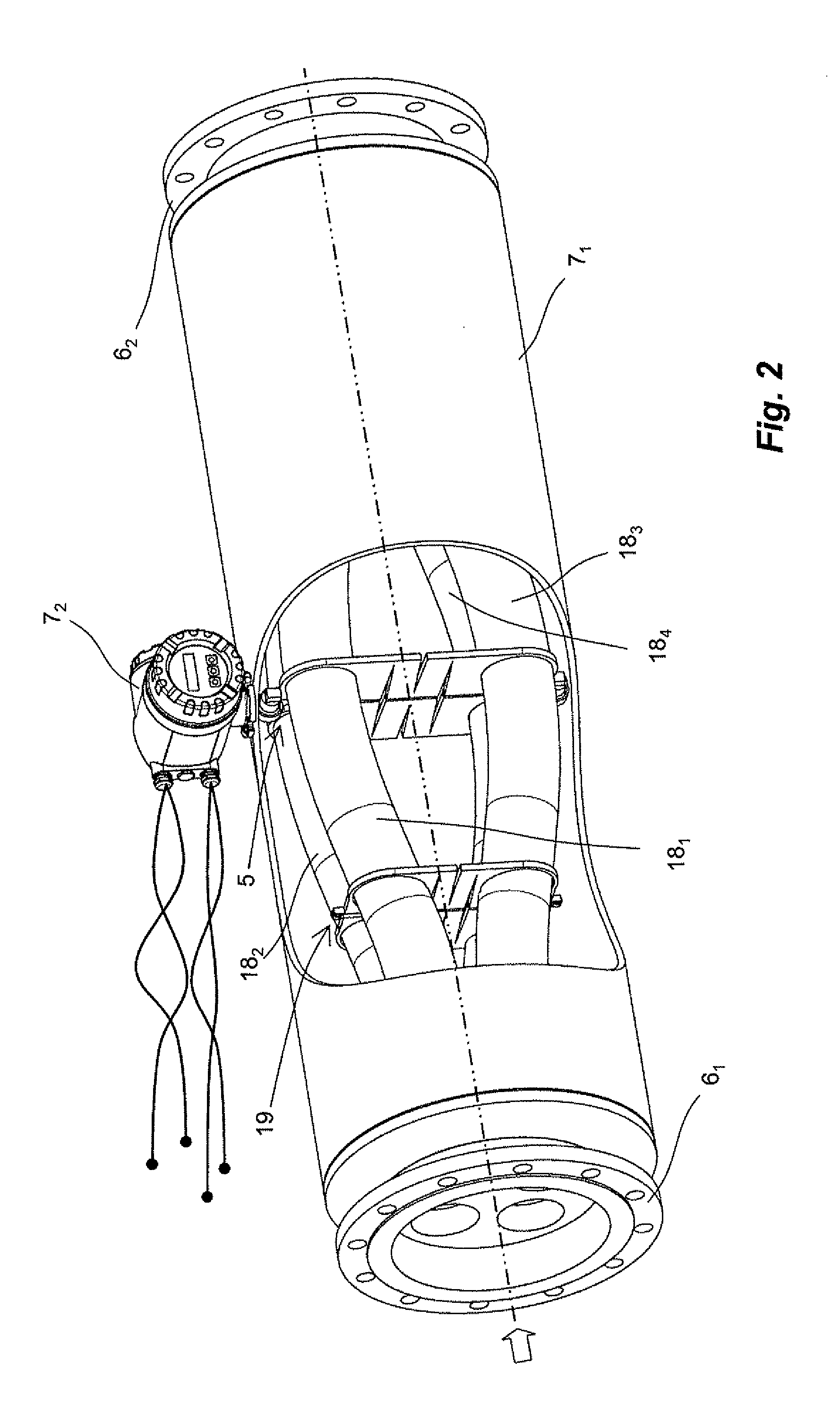
[0064]FIGS. 1, 2 show, schematically, an in-line measuring device 1, especially an in-line measuring device embodied as a Coriolis, mass flow, and / or density, measuring device, which serves for registering a mass flow m of a medium flowing in a pipeline (not shown) and for representing such in a mass flow, measured value representing this mass flow instantaneously. The medium can be practically any flowable material, for example, a powder, a liquid, a gas, a vapor, or the like. Altern...


PUM

PropertyMeasurementUnit
lengthaaaaaaaaaa
lengthaaaaaaaaaa
lengthaaaaaaaaaa

Abstract

The measuring transducer comprises: a transducer housing, of which an inlet-side, housing end is formed by means of a flow divider including four flow openings spaced, and an outlet-side, formed by means of a flow divider including four flow openings spaced, from one another. A tube arrangement including four curved measuring tubes connected to the flow dividers for guiding flowing medium along flow paths connected in parallel. Each measuring tubes opens with an inlet-side, measuring tube end into one of the flow openings of the flow divider and with an outlet-side, measuring tube end into one the flow openings of the flow divider. The two flow dividers are embodied and arranged in the measuring transducer, so that the tube arrangement extends both between a first and a second of the measuring tubes and between a third and a fourth of the measuring tubes. An imaginary longitudinal-section plane, with respect to which the tube arrangement is mirror symmetric and perpendicular to the imaginary longitudinal-section plane, an imaginary longitudinal-section plane, with respect to which the tube arrangement likewise is mirror symmetric. An electromechanical exciter mechanism of the measuring transducer serves for producing and/or maintaining mechanical oscillations of the four measuring tubes.

Description

CROSS-REFERENCES[0001]This application is a nonprovisional application based on U.S. Provisional application 61 / 282,132, which was filed on Dec. 22, 2009, and based on U.S. Provisional application 61 / 344,561, which was filed on Aug. 20, 2010; and priorities are also claimed of German application 102009055069.0 filed on Dec. 21, 2009, and of German application 102010039627.3 filed on Aug. 20, 2010.FIELD OF THE INVENTION[0002]The invention relates to a measuring transducer of vibration-type for measuring a medium flowably guided in a pipeline, especially a gas, liquid, powder or other flowable material, especially for measuring a density and / or a mass flow rate, especially also a mass flow integrated over a time interval, of a medium flowing in a pipeline, at least at times, with a mass flow rate of more than 1000 t / h, especially more than 1500 t / h. Additionally, the invention relates to an in-line measuring device including such a measuring transducer.BACKGROUND OF THE INVENTION[0003...

Claims


Application Information

Patent Timeline
Patent Type & Authority Applications(United States)
IPC IPC(8): G01N9/32G01F1/84
CPCG01F1/84G01F1/849G01F1/8477G01F1/8413G01F15/02G01F25/10
Inventor BITTO, ENNIOHUBER, CHRISTOFBRAUN, MARCELRIEDER, ALFREDSCHUTZE, CHRISTIAN
Owner ENDRESS HAUSER FLOWTEC AG
Why Eureka
Try Eureka