5-Wire resistive touch screen pressure measurement circuit and method

a resistive touch screen and pressure measurement technology, applied in the field of 5-wire resistive touch screen pressure measurement circuit and method, can solve the problems of inability to provide a highly conductive (e.g., metal) contact wiper layer, the associated touch screen system may erroneously interpret the touch location or erroneously interpret the touch location, and users may inadvertently touch the screen surface. , to achieve the effect of improving the verification of signatur

Active Publication Date: 2011-07-14
TEXAS INSTR INC
View PDF5 Cites 62 Cited by
  • Summary
  • Abstract
  • Description
  • Claims
  • Application Information

AI Technical Summary

Benefits of technology

[0025]It is another object of the invention to provide a touch screen system capable of providing improved signature verification by utilizing touch point contact resistance in a 5-wire touch screen.

Problems solved by technology

Unfortunately, it is not presently practical to provide a highly conductive (e.g., metal) contact wiper layer 11 that is sufficiently transparent for the LCD backlighting applications in which touch screens often are utilized.
Touch screen users may occasionally bump a nearby article that imparts mechanical vibration to a touch screen that can cause the associated touch screen system to erroneously interpret touch location or erroneously interpret the vibration as an intentional touch.
Also, users may inadvertently touch the screen surface.
The prior 5-wire touch screen systems can only measure x- and y-coordinates, lack any method for obtaining third-coordinate or pressure data, and have limited capability for performing certain functions, such as signature verification, in which the pressure applied to provide a valid signature can be very significant.

Method used


Image

  • 5-Wire resistive touch screen pressure measurement circuit and method
  • 5-Wire resistive touch screen pressure measurement circuit and method
  • 5-Wire resistive touch screen pressure measurement circuit and method

Examples


Embodiment Construction

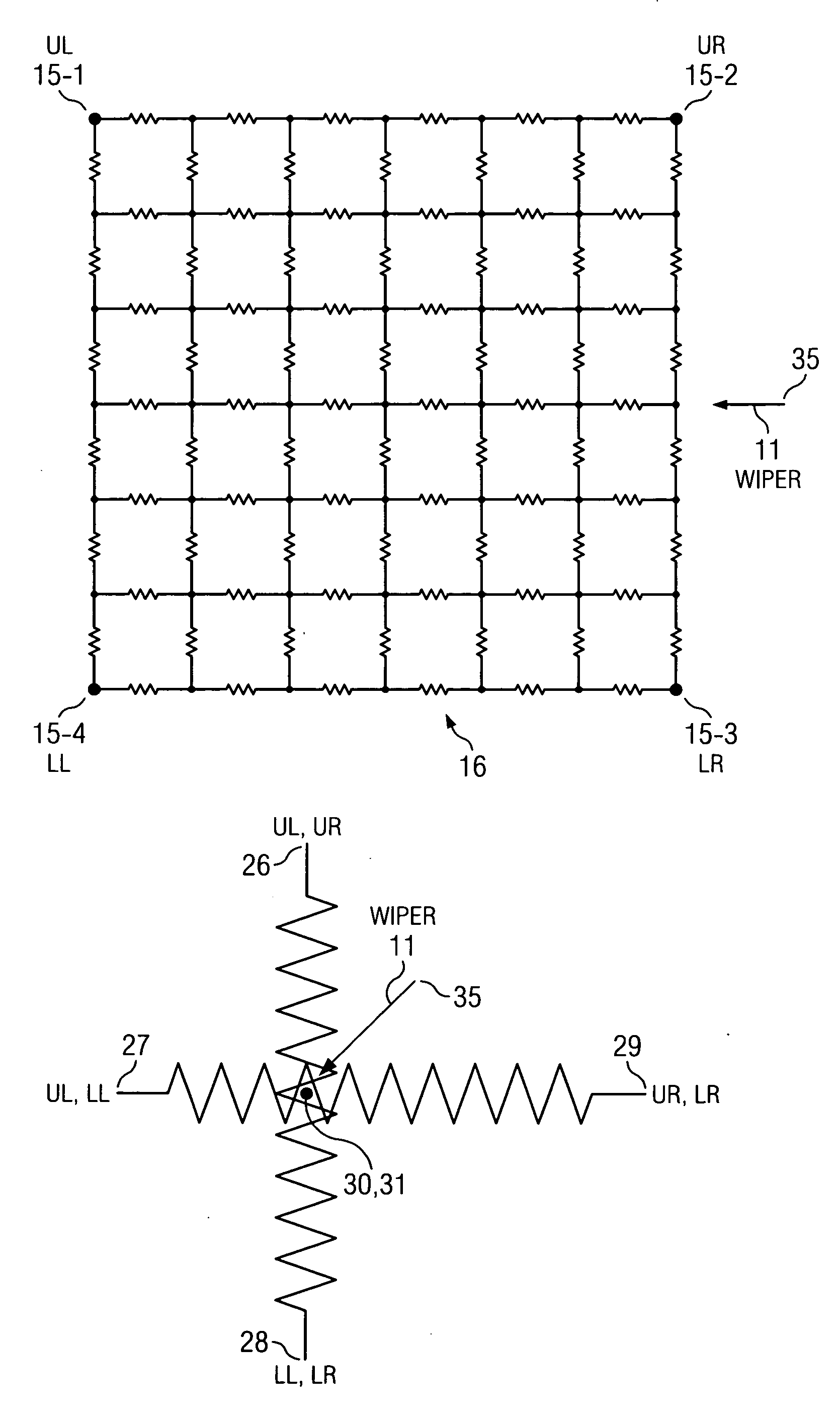
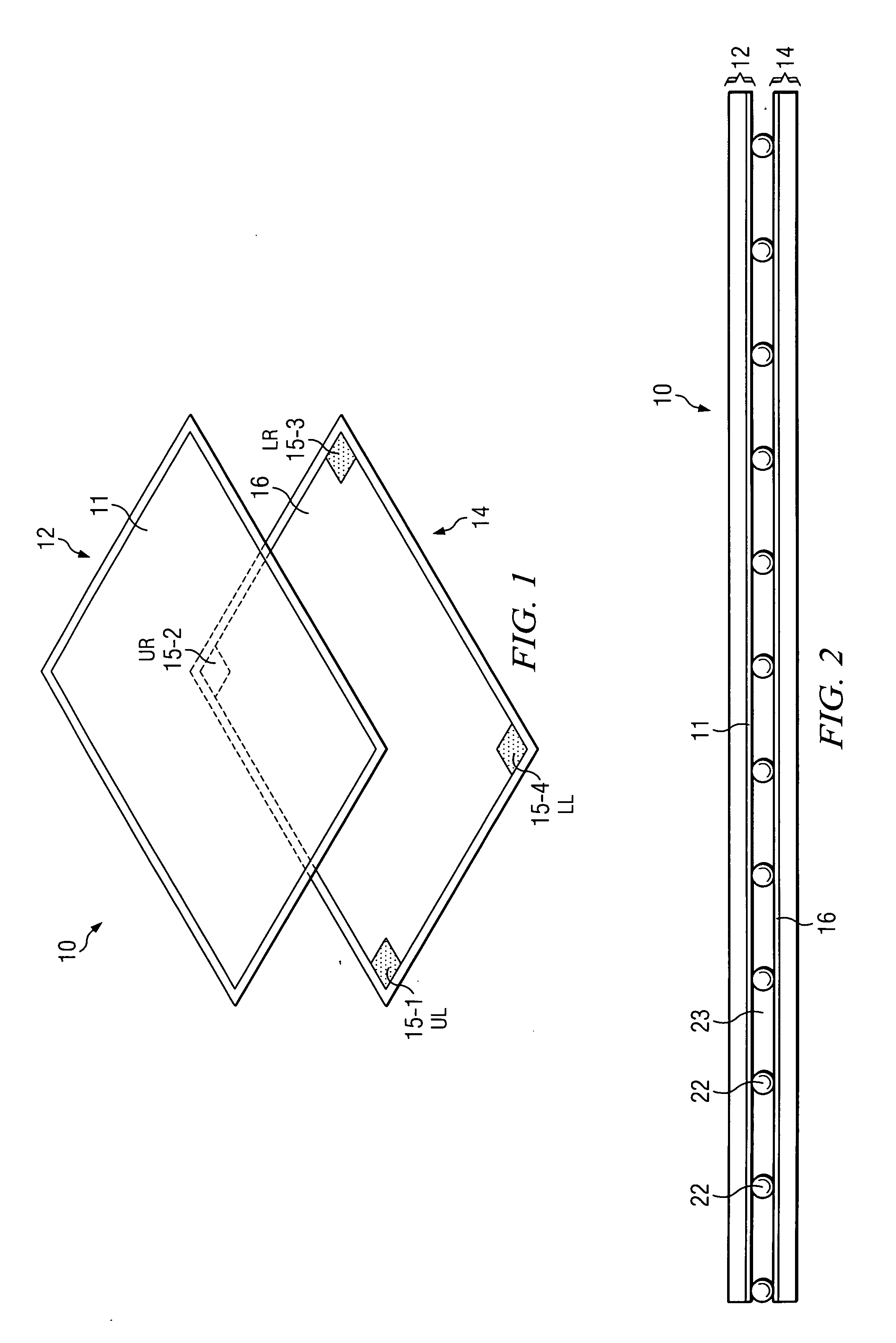
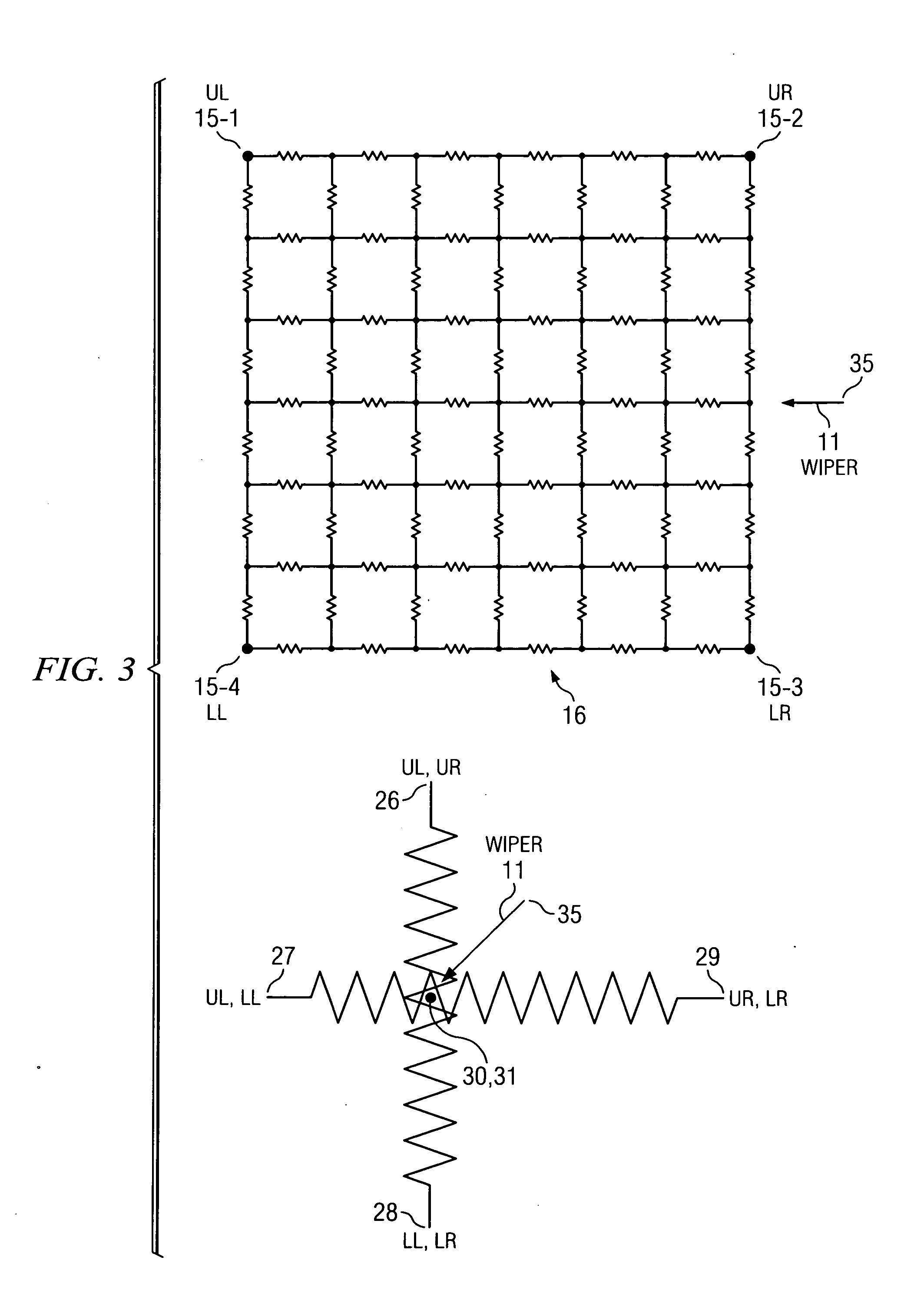
[0054]FIGS. 7A and 7B show an equivalent circuit of a touch screen 10 (FIG. 1) on which a touch pressure has been applied on a small area 31 of wiper layer 11, thereby pressing it against the surface of top layer 12 to thereby form a resistive touch pressure contact area 30 on resistive layer 16. Touch pressure contact areas 30 and 31 result in a contact resistance RZ (or a very substantial change in the contact resistance RZ) between wiper 11 and resistive layer 16. Dashed line 33 surrounds the touch pressure contact area resistance RZ as diagrammatically illustrated in FIGS. 7A and 7B. Resistive layer 16 (also see FIG. 2) is represented as a rectangular grid of discrete resistors with terminals UL, UR, LL, and LR in its upper left, upper right, lower left, and lower right corners corresponding to conductive pads 15-1, 15-2, 15-4, and 15-3, respectively, as shown in the exploded view in prior Art FIG. 1.

[0055]Pressure contact area resistance RZ is connected in series between resist...


PUM


Abstract

A 5-wire touch screen system includes a touch screen (10) including a wiper (11) and a resistive layer (16) aligned with the wiper and first (UL), second (UR), third (LR), and fourth (LL) resistive layer contacts, wherein a touch on the screen presses a small portion of the wiper against the resistive layer, producing a touch resistance (RZ) between them at a touch point on the resistive layer. The wiper and various contacts are selectively coupled to first (VDD) and second (GND) reference voltages, respectively, to generate an analog touch voltage (VZ) at the touch point. The wiper and various contacts are selectively coupled to an analog input (56) and a reference voltage input of an ADC (48) for converting the touch voltage (VZ) to a digital representation. Analog voltages (VX) and (VY) at the touch point are converted to corresponding digital representations by the ADC.

Description

BACKGROUND OF THE INVENTION[0001]The present invention relates generally to 5-wire touch screens, and more particularly to systems and methods for accurately determining touch pressure / force applied on 5-wire touch screens.[0002]FIG. 1 shows an exploded isometric diagram of a conventional 5-wire resistive touch screen 10 including a transparent bottom layer 14, coated with resistive film 16 and four conductive corner pads 15-1, 15-2, 15-3 and 15-4 that can be connected to an outside contact terminal, and a top layer 12. (The layers need to be transparent to allow display or LCD (liquid crystal display) backlighting to pass through.) FIG. 2 shows a section view of an implementation of the assembled version of the exploded view of touch screen 10 in FIG. 1, wherein top layer 12 typically is formed of polyester or polyethylene terephthalate (PET) and is coated underneath with highly conductive (e.g., metal) transparent material to form wiper layer 11 (also referred to simply as “wiper ...

Claims


Application Information

Patent Timeline
Patent Type & Authority Applications(United States)
IPC IPC(8): G06F3/041
CPCG06F3/045G06F2203/04101G06F2203/04112
Inventor FANG, WENDY X.WANG, ING-YIH JAMES
Owner TEXAS INSTR INC
Why Eureka
Try Eureka