Magnetoresistive device

a magnetoresistive device and magnetic field technology, applied in static storage, information storage, digital storage, etc., can solve the problems of high current density, increased power consumption, increased magnetism field required to switch the free layer, etc., and achieve the effect of reducing power consumption

Active Publication Date: 2011-07-14
HITACHI LTD +2
View PDF13 Cites 82 Cited by
  • Summary
  • Abstract
  • Description
  • Claims
  • Application Information

AI Technical Summary

Benefits of technology

[0027]The method may comprise exclusively applying the electric field pulse to the ferromagnetic region so as to cause magnetisation of the ferromagnetic region to switch between the first and second orientations. The method may comprise arranging for magnetisation of the ferromagnetic region to switch between the first and second orientations without applying a magnetic field pulse. Using only an electric field pulse to cause magnetisation of the ferromagnetic region to switch between the first and second orientations or not using a magnetic field pulse to assist switching helps to minimise power consumption.

Problems solved by technology

However, this arrangement suffers the problem that as the size of the cell decreases, the magnetic field required to switch the free layer increases and so power consumption also increases.
A drawback, however, of spin transfer switching is that a high current density (e.g. of the order of 108 Acm−2) is needed to trigger the reversal process.
Although the power consumption of the switching current pulse is reduced, the overall power consumption (i.e. including the power consumption of the pre-charging current) is still quite large.
This limits the potential for scalability and reducing power consumption.

Method used


Image

  • Magnetoresistive device
  • Magnetoresistive device
  • Magnetoresistive device

Examples


Embodiment Construction

Electric Field Pulse Induced Magnetization Reversal

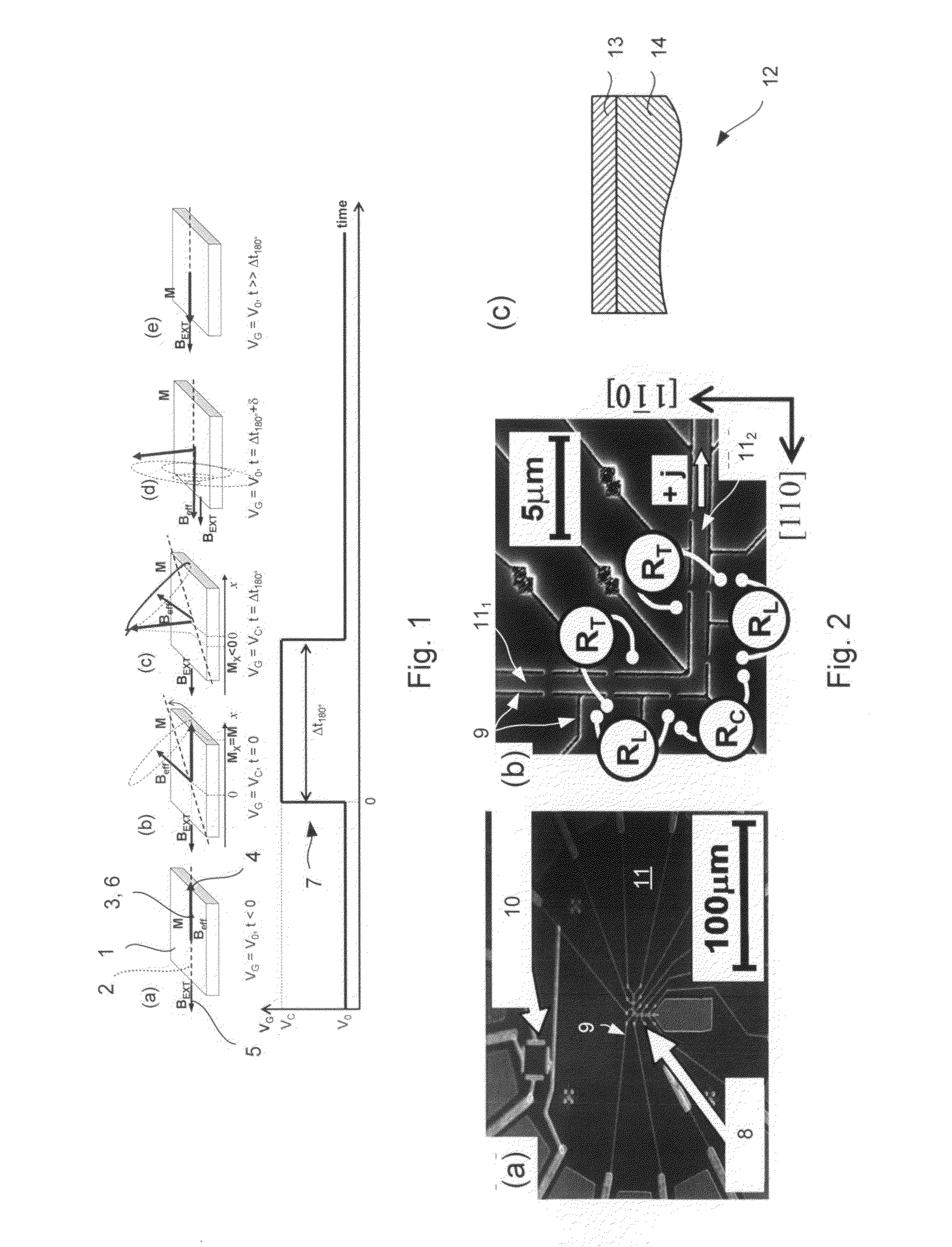
[0105]Referring to FIG. 1, a ferromagnetic element 1 of a magnetoresistive device in accordance with the present invention is shown. The ferromagnetic element 1 is assumed to have homogenously distributed magnetization, although this need not necessarily be the case.

[0106]The ferromagnetic element 1 exhibits magnetic anisotropy defining a magnetic easy axis 2. Magnetic anisotropy may arise as a result of, inter alia, the shape of the element and / or crystal structure. For example, the element 1 may be elongate and so the magnetic easy axis 2 may be aligned along a longitudinal axis.

[0107]Magnetisation 4 of the element 1 is aligned along a magnetic easy axis 2.

[0108]An external magnetic field 5 may optionally be applied to support precessional switching and, depending on orientation, to stabilize re-orientation of the magnetisation 3. For example, the external magnetic field 5 may be applied globally to an array of ferromagnetic eleme...


PUM


Abstract

A method of operating a magnetoresistive device is described. The device comprises a ferromagnetic region configured to exhibit magnetic anisotropy and to allow magnetisation thereof to be switched between at least first and second orientations and a gate capacitively coupled to the ferromagnetic region. The method comprises applying an electric field pulse to the ferromagnetic region so as to cause orientation of magnetic anisotropy to change for switching magnetisation between the first and second orientations.

Description

FIELD OF THE INVENTION[0001]The present invention relates to a magnetoresistive device.BACKGROUND[0002]Magnetic random access memory (MRAM) has several advantages over other types of non-volatile memory, such as Flash memory. For example, MRAM usually consumes less power and is faster to read and write data. MRAM also offers a promising alternative to some forms of volatile memory, such as dynamic random access memory (DRAM).[0003]A conventional MRAM cell typically includes a magnetoresistive element which has a pair of ferromagnetic layers separated by a non-magnetic layer. One of the ferromagnetic layers has a relatively low coercivity and the other has a relatively high coercivity. The low- and high-coercivity layers are usually referred to as “free” and “pinned” layers respectively.[0004]To store data in the cell, an external magnetic field is applied which orientates the magnetisation of the free layer. After the magnetic field is removed, the orientation of the magnetisation i...

Claims


Application Information

Patent Timeline
Patent Type & Authority Applications(United States)
IPC IPC(8): G11C11/00
CPCG11C11/1675G11C11/16G11C11/161G11C11/165
Inventor WUNDERLICH, JOERGZEMEN, JANCHAPPERT, CLAUDEGALLAGHER, BRYANDEVOLDER, THIBAUTWILLIAMS, DAVID
Owner HITACHI LTD
Why Eureka
Try Eureka