

Transmission rate control device and transmission rate control method
a transmission rate and control device technology, applied in data switching networks, instruments, frequency-division multiplexes, etc., can solve problems such as congestion on the network, overseas line l is a bottleneck, and tfrc cannot immediately change the transmission rate to an appropriate valu
- Summary
- Abstract
- Description
- Claims
- Application Information
AI Technical Summary
Benefits of technology
Problems solved by technology
Method used
Image

Examples
first embodiment
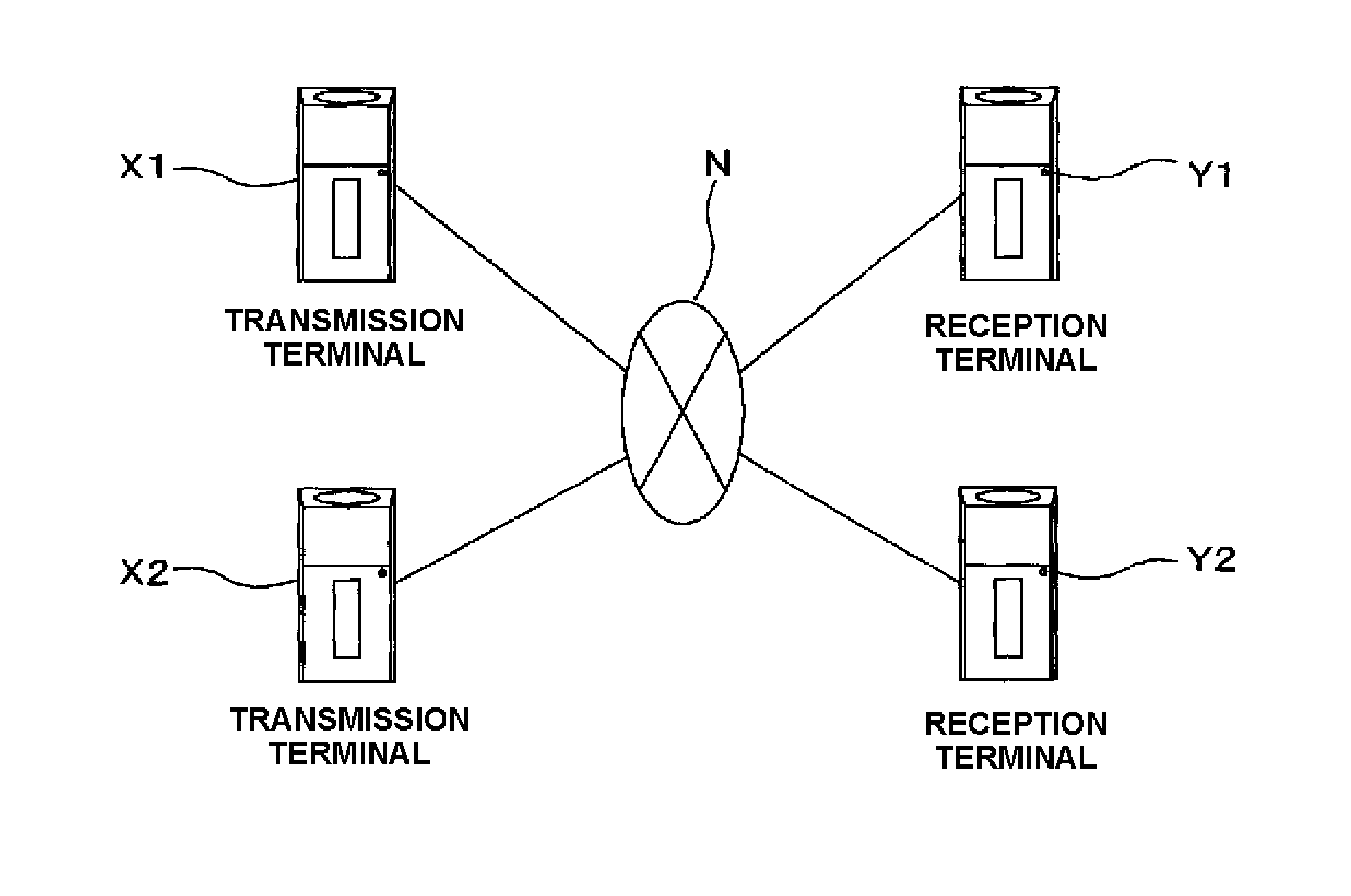
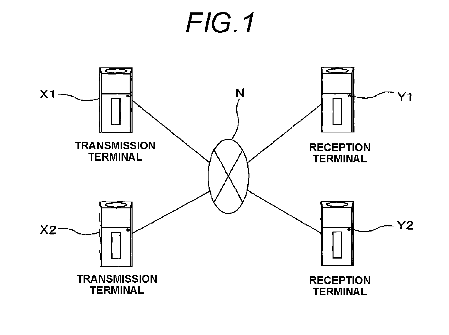
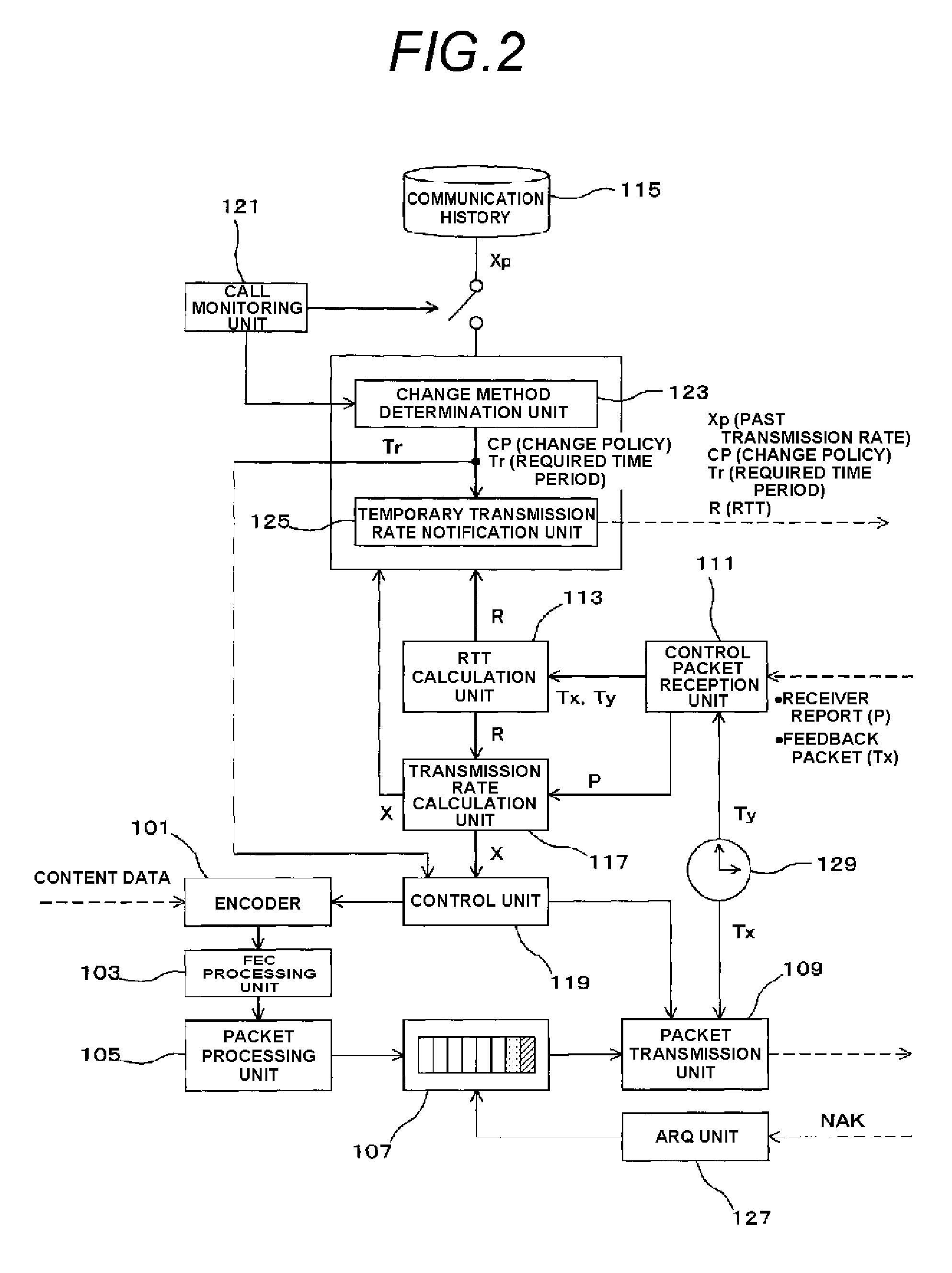
[0033]FIG. 2 is a block diagram showing the internal configuration of the transmission terminal X1 in a first embodiment. As shown in FIG. 2, the transmission terminal X1 in the first embodiment includes an encoder 101, a redundant code processing unit (FEC processing unit) 103, a packet processing unit 105, a buffer 107, a packet transmission unit 109, a control packet reception unit 111, an RTT calculation unit 113, a communication history storage unit 115, a transmission rate calculation unit 117, a control unit 119, a call monitoring unit 121, a change method determination unit 123, a temporary transmission rate notification unit 125, an ARQ unit 127, and a clock 129.
[0034]The encoder 101 encodes content data such as video and audio data in accordance with a predetermined coding rate. The redundant code processing unit 103 generates a redundant code for enabling the reception terminal Y1 to perform error detection or error correction such as the FEC (Forward Error Correction), f...
second embodiment
[0068]FIG. 5 is a block diagram showing the internal configuration of the transmission terminal X2 in a second embodiment. The transmission terminal X2 in FIG. 5 includes the encoder 101, the redundant code processing unit (FEC processing unit) 103, the packet processing unit 105, the buffer 107, the packet transmission unit 109, a control packet reception unit 301, the RTT calculation unit 113, the communication history storage unit 115, a transmission rate calculation unit 303, the control unit 119, a call monitoring unit 305, the change method determination unit 123, a target loss event rate calculation unit 307, a temporary loss event interval calculation unit 309, a loss event rate calculation unit 311, the ARQ unit 127, and the clock 129. In FIG. 5, the components which are common to FIG. 2 showing the transmission terminal X1 in the first embodiment are denoted by the same reference numerals.
[0069]The target loss event rate calculation unit 307, the temporary loss event inter...
third embodiment
[0077]The transmission terminals X1, X2 in the above-described embodiments include the redundant code processing unit 103 and the ARQ unit 127, and the reception terminals Y1, Y2 include the redundant code processing unit 207 and the ARQ unit 227. As described above, the redundant code processing unit 103 which is provided in the transmission terminals X1, X2 generates a redundant code from encoded content data, adds the redundant code to the encoded content data, and outputs the addition result. The redundant code processing unit 207 of the reception terminals Y1, Y2 periodically performs error detection or error correction on the encoded content data, by using the read redundant code.
[0078]By contrast, the ARQ unit 227 which is included in the transmission terminals X1, X2 receives the retransmission request (NAK) of the RTP packet which is transmitted from the reception terminals Y1, Y2. When the packet indicated by the received NAK is accumulated in the buffer 107, the ARQ unit ...
PUM
 Abstract
Description
Claims
Application Information