
Base station device

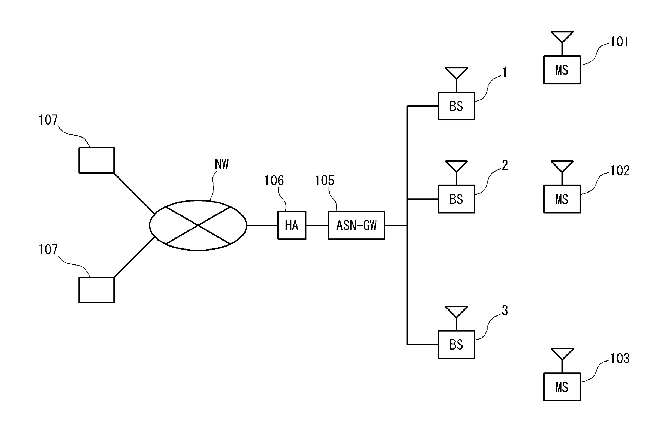
Inactive Publication Date: 2011-07-14
SUMITOMO ELECTRIC IND LTD
View PDF22 Cites 47 Cited by
  • Summary
  • Abstract
  • Description
  • Claims
  • Application Information

AI Technical Summary

Benefits of technology

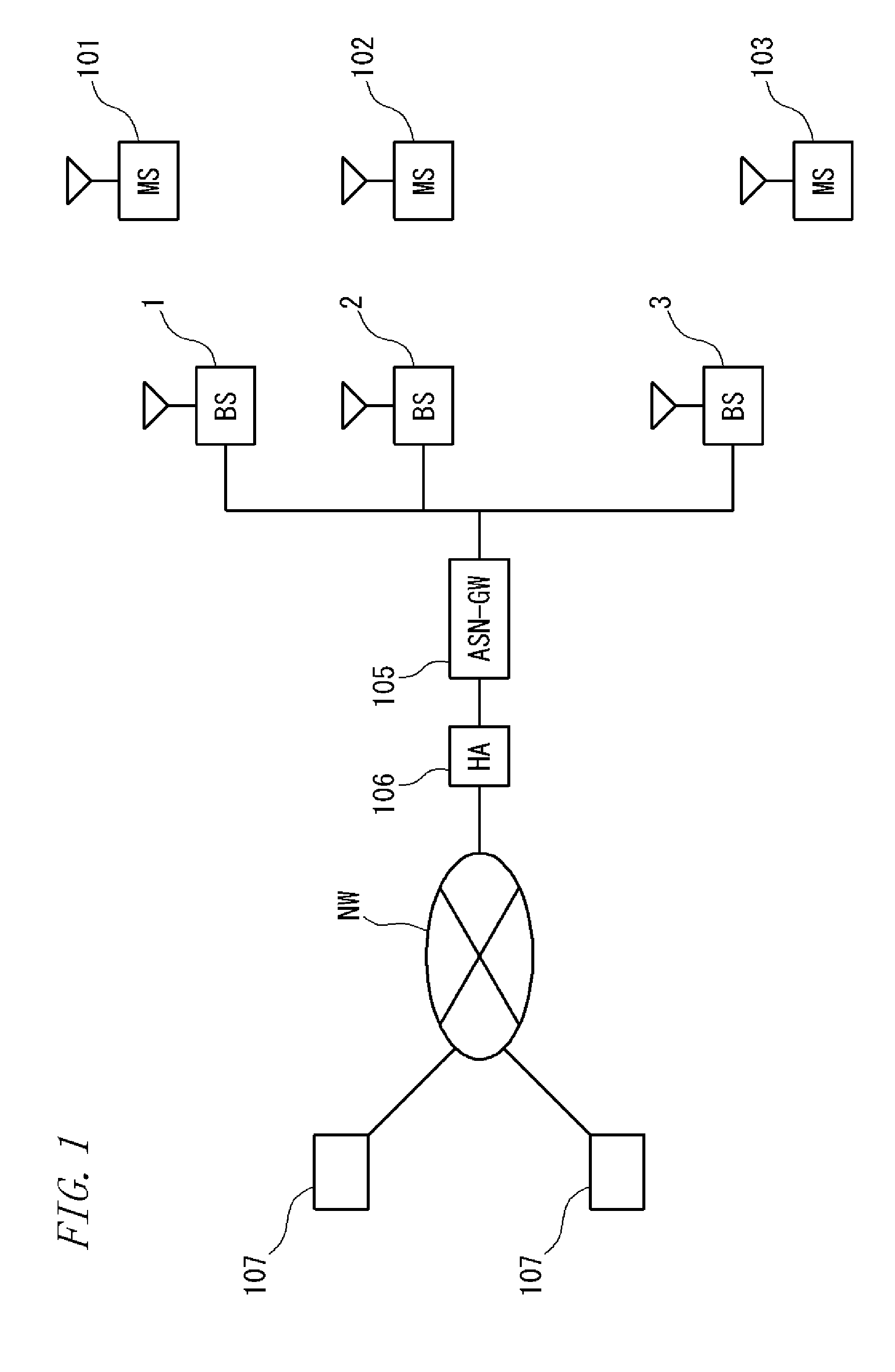
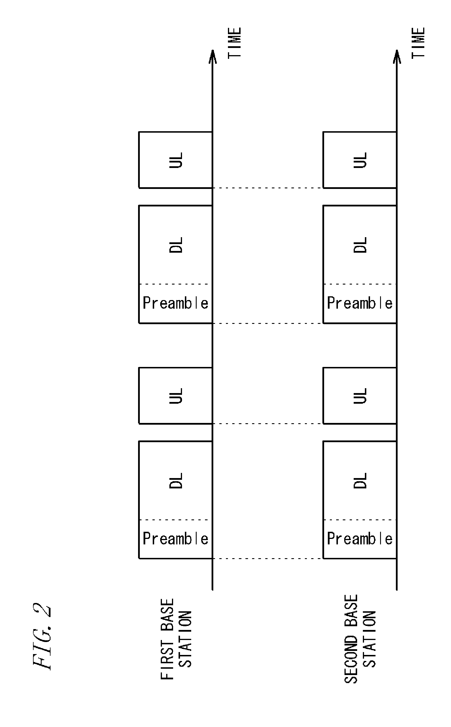
[0023]In addition, when the terminal device MS2 performs macrodiversity or spatial multiplexing transmission using signals transmitted from the plurality of base station devices BS1 and BS2, if the transmission timings of the base station devices BS1 and BS2 do not coincide with each other, the effect decreases.
[0051]Then, the base station device can achieve over-the-air synchronization with another base station device, based on the downlink signal from another base station device which is received by the second receiving unit.
[0052]In a communication system including a plurality of the above-described base station devices, the plurality of base station devices can be configured to simultaneously transmit information of the same content to terminal devices. In frequency-division duplex, also, by achieving synchronization between base station devices, even if the plurality of base station devices transmit information of the same content to terminal devices at once, the terminal devices can receive the information without any trouble. Accordingly, broadcast transmission from a plurality of base station devices, or macrodiversity or spatial division multiplexing transmission using signals transmitted from a plurality of base station devices can be performed.
[0055]Hence, in the present invention, using the fact that the second receiving unit is configured to be compatible with the frequency of a downlink signal, the second receiving unit is also used as the circuit that provides the output signal from the amplifier, to the distortion compensating unit, whereby the circuits are formed as one common unit. By forming the circuits as one common unit, even if the second receiving unit is provided, an increase in circuit size can be suppressed.
[0065]It is preferred that the base station device is configured to: perform a first pattern recognition by one of the first recognizing unit and the second recognizing unit that recognizes a pattern of a known signal with a small number of patterns that can be taken by the signal; and perform, after a pattern is recognized by the first pattern recognition, a second pattern recognition by one of the first recognizing unit and the second recognizing unit that recognizes a pattern of a known signal with a large number of patterns that can be taken by the signal. In this case, pattern recognition can be performed easily or rapidly.

Problems solved by technology

In an OFDM signal, since subcarriers are arranged densely and subcarrier spacings are small, when there is a large error in carrier frequency between the signal transmitting and receiving sides, OFDM demodulation characteristics deteriorate.

Method used


Image

  • Base station device
  • Base station device
  • Base station device

Examples


fourth embodiment

2.4 Fourth Embodiment

[0285]FIG. 16 shows a configuration of a slave BS 2001b according to a fourth embodiment. As with slave BSs 2001b according to the already described embodiments, this slave BS 2001b can also receive a signal transmitted from a master BS 2001a, to perform over-the-air synchronization. The slave BS 2001b includes an antenna 2010, a first receiving unit (superheterodyne receiver) 2011, a second receiving unit (superheterodyne receiver) 2012, and a transmitting unit 2013. In addition, the slave BS 2001b includes a circulator 2014. Note that those points that are not particularly described in the fourth embodiment are the same as those in the already described embodiments.

[0286]As such, the basic configuration of the slave BS 2001b in the fourth embodiment is the same as that of slave BSs 2001b according to the already described embodiments. Particularly, the slave BS 2001b in the fourth embodiment is similar to the slave BS 2001b according to the second embodiment i...

fifth embodiment

2.5 Fifth Embodiment

[0302]FIG. 18 shows a configuration of a slave BS 2001b according to a fifth embodiment. In the fifth embodiment, as with the slave BS 2001b in the second embodiment shown in FIG. 14, a first receiving unit 2011 and a second receiving unit 2012 are provided independently of each other, and the first receiving unit 2011 and the second receiving unit 2012 are configured as direct conversion receivers. That is, the first receiving unit 2011 and the second receiving unit 2012 include band-pass filters 2111 and 2121 that allow only an uplink signal or a downlink signal received by an antenna 2010 to pass therethrough; and amplifiers 2112 and 2122 that amplify the signals having passed through the filters 2111 and 2121. Furthermore, the first receiving unit 2011 and the second receiving unit 2012 include orthogonal demodulators 2118 and 2128 that demodulate the outputs from the amplifiers 2112 and 2122 into demodulated signals I and Q; and A / D converting units 2117a, 2...

sixth embodiment

2.6 Sixth Embodiment

[0305]FIG. 19 shows a configuration of a slave BS 2001b according to a sixth embodiment. In the sixth embodiment, a common unit 2023 which is similar to the common unit 2023 in the first receiving unit 2011 and the second receiving unit 2012 in the fourth embodiment shown in FIG. 16 is provided in the first receiving unit 2011 and the second receiving unit 2012 which are of a direct conversion system in the fifth embodiment shown in FIG. 18.

[0306]A first receiving unit 2011 in the sixth embodiment includes, as circuit elements specific to the first receiving unit 2011, a filter (band-pass filter) 2111 that allows only a signal with the frequency fu to pass therethrough; and an amplifier 2112 that amplifies the signal outputted from the filter 2111.

[0307]A second receiving unit 2012 includes, as circuit elements specific to the second receiving unit, a filter (band-pass filter) 2121 that allows only a signal with the frequency fd to pass therethrough; and an ampli...


PUM


Abstract

While a clock generated by a built-in clock generator is used as a reference signal for determining a carrier frequency of a transmit signal, carrier frequency synchronization is achieved between base stations. A base station device is configured to perform wireless communication with a terminal device. In the base station device, accuracy of a carrier frequency of an OFDM signal is affected by accuracy of a clock frequency generated by a built-in clock generator 18. The base station device receives an OFDM signal transmitted from another base station device while transmission to the terminal device is stopped, estimates a carrier frequency offset of the OFDM signal, and corrects a carrier frequency of an OFDM signal to be transmitted to the terminal device.

Description

TECHNICAL FIELD[0001]The present invention relates to a base station device.BACKGROUND ART[0002]In a wireless communication system where mobile terminals can perform communication, such as WiMAX (Worldwide Interoperability for Microwave Access), large numbers of base stations are installed at various locations. Mobile terminals present in an area (cell) covered by a base station can perform communication with the base station that covers the area.[0003]With the movement of a mobile terminal, a base station which is a communication partner of the mobile terminal changes. Upon the change of the base station, the mobile terminal simultaneously receives signals transmitted from two base stations (a serving base station and a target base station).[0004]Hence, in order to smoothly perform base-station-to-base-station movement of the mobile terminal, inter-base-station synchronization where transmission timings coincide with each other between adjacent base stations needs to be ensured.[00...

Claims


Application Information

Patent Timeline
IPC IPC(8): H04W88/08
CPCH04W56/0015H04L27/2675H04L27/2655H04L27/2657H04W56/0035H04L25/0202H04W88/08H04B17/11
Inventor YAMAMOTO, TAKASHIOKADA, YOJI
Owner SUMITOMO ELECTRIC IND LTD
Learn More