
Susceptor, coating apparatus and coating method using the susceptor

a susceptor and coating apparatus technology, applied in coatings, metal-working machine components, manufacturing tools, etc., can solve the problems of affecting the transfer of the wafer, affecting the electrical characteristics of the formed epitaxial film, and affecting the transmission of the wafer

Active Publication Date: 2011-07-14
NUFLARE TECH INC
View PDF8 Cites 159 Cited by
  • Summary
  • Abstract
  • Description
  • Claims
  • Application Information

AI Technical Summary

Benefits of technology

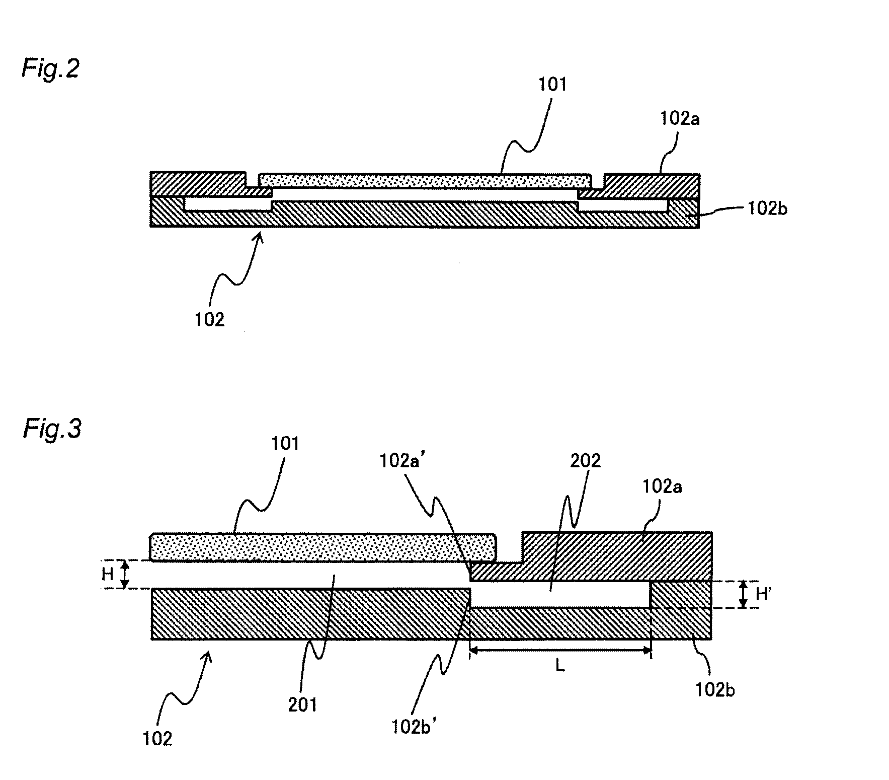
[0019]According to other aspect of the present invention, in a method of forming a predetermined film on a substrate in a coating chamber while heating the substrate, a peripheral portion of the substrate is supported by an annular first susceptor portion. A second susceptor portion is disposed so that the second susceptor portion is in contact with a peripheral portion of the first susceptor portion and covers the opening of the first susceptor portion, and so that, when the substrate is supported on the first susceptor portion, a first gap of a predetermined size is formed between the substrate and the second susceptor portion and a second gap of a size substantially equal to the predetermined size and directly connected to the first gap is formed between the first and second susceptor portions so as to be able to uniformly heat the substrate.

Problems solved by technology

This structure is disadvantageous in that the wafer might be contaminated with contaminants such as metal atoms originating from the heating unit and the rotary portion, resulting in degradation of the electrical characteristics of the formed epitaxial film.
This film acts to attach the wafer to the susceptor, which may cause a crystal defect called a “slip” in the wafer as well as hampering the transfer of the wafer.
The slip acts to warp the wafer and generate a leakage in the IC device, thereby greatly reducing the yield of the IC device.
Another problem arises when the bottom surface of the wafer is heated in order to form an epitaxial film on its top surface.
In this case, however, another problem arises, as described below.
Consequently, the temperature distribution across the silicon wafer 301 is not uniform and, hence, the thickness of the formed epitaxial film is not uniform.

Method used


Image

  • Susceptor, coating apparatus and coating method using the susceptor
  • Susceptor, coating apparatus and coating method using the susceptor
  • Susceptor, coating apparatus and coating method using the susceptor

Examples


Embodiment Construction

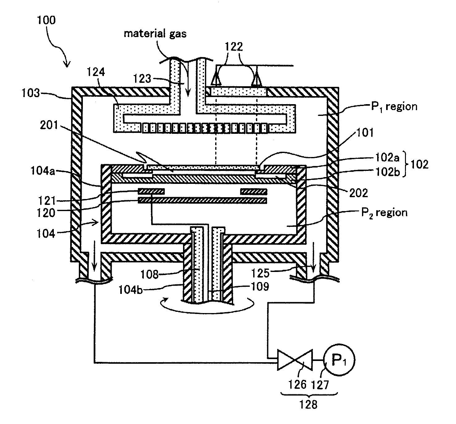
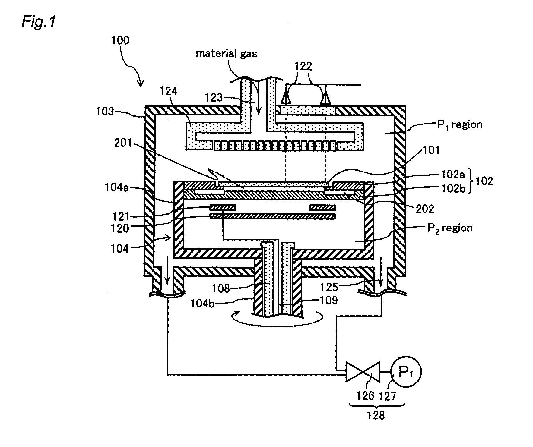
[0028]FIG. 1 is a schematic cross-sectional view of a coating apparatus 100 of the single wafer processing type according to an embodiment of the present invention.

[0029]The substrate of the present embodiment described herein is a silicon wafer 101. However, the embodiment is not limited to this particular substrate, but may be applied to wafers of other suitable material depending on the application intended.

[0030]The coating apparatus 100 includes a chamber 103 serving as a coating chamber.

[0031]A gas supply portion 123 is provided at the top of the chamber 103 to supply a material gas to the surface of the silicon wafer 101 in a heated state to form a crystalline coating on the surface. Further, a shower plate 124 having a large number of material gas discharge holes formed therein is connected to the gas supply portion 123. The shower plate 124 is disposed to face the surface of the silicon wafer 101 to supply a material gas thereto.

[0032]A plurality of gas exhaust portions 125...


PUM

PropertyMeasurementUnit
Angular velocityaaaaaaaaaa
Sizeaaaaaaaaaa

Abstract

In accordance with the embodiment of the present invention, there is provided a susceptor which includes an annular first susceptor portion for supporting the peripheral portion of a silicon wafer and further includes a second susceptor portion provided in contact with the peripheral portion of the first susceptor portion and covering the opening of the first susceptor portion. The second susceptor portion is disposed so that, when the silicon wafer is supported on the first susceptor portion, a gap of a predetermined size is formed between the silicon wafer and the second susceptor portion, and so that another gap of a size substantially equal to the predetermined size and directly connected to the above gap is formed between the first susceptor portion and the second susceptor portion.

Description

CROSS-REFERENCE TO RELATED APPLICATION [0001]The entire disclosure of a Japanese Patent Application No. 2009-156809, filed on Jul. 1, 2009 including specification, claims, drawings and summary, on which the Convention priority of the present application is based, are incorporated herein by reference in its entirety.BACKGROUND OF THE INVENTION [0002]1. Field of the Invention[0003]The present invention relates to a susceptor and to a coating apparatus and coating method using the susceptor.[0004]2. Background Art[0005]Epitaxial growth techniques are used to manufacture semiconductor devices requiring a relatively thick crystalline coating or film, such as power devices, including IGBTs (Insulated Gate Bipolar Transistors).[0006]In order to produce an epitaxial wafer having a considerable coating thickness with high yield, it is necessary to continuously bring a fresh supply of material gas into contact with the uniformly heated surface of the wafer and thereby increase the coating spe...

Claims


Application Information

Patent Timeline
IPC IPC(8): C23C16/46C23C16/458C23C16/00
CPCC23C16/4586H01L21/68785H01L21/68735H01L21/0262
Inventor HIGASHI, SHINYAHIRATA, HIRONOBU
Owner NUFLARE TECH INC
Learn More