Carrier, developer using the carrier, and developing device, image forming method, image forming apparatus and process cartridge using the developer

a carrier and developer technology, applied in the field of carriers, can solve the problems of forming abnormal images, and increasing the chance of occurrence of offset problems

Active Publication Date: 2011-07-14
RICOH KK
View PDF23 Cites 37 Cited by
  • Summary
  • Abstract
  • Description
  • Claims
  • Application Information

AI Technical Summary

Problems solved by technology

However, the contact heat fixing methods have a drawback in that they often cause an offset problem, in which a part of a toner image is adhered to a fixing member, and the adhered toner is transferred again to the image or another image, resulting in formation of an abnormal image, because the melted toner image is contacted with the fixing member upon application of heat and pressure thereto.
Although the fixing methods are effective in preventing occurrence of the offset problem, the methods have a drawback in that, since an oil applicator has to be provided, the fixing device becomes unacceptably large.
However, since full color image forming apparatuses preferably produce glossy images as mentioned above, color toners used therefor preferably have a lower viscoelasticity than toners used for monochrome image forming apparatuses, thereby increasing the chance of occurrence of the offset problem.
Therefore, it is difficult for full color image forming apparatuses to use an oil-less fixing device.
In addition, toner includi

Method used


Image

  • Carrier, developer using the carrier, and developing device, image forming method, image forming apparatus and process cartridge using the developer
  • Carrier, developer using the carrier, and developing device, image forming method, image forming apparatus and process cartridge using the developer
  • Carrier, developer using the carrier, and developing device, image forming method, image forming apparatus and process cartridge using the developer

Examples


example 1

(Preparation of Coated Carrier)

1. Preparation of Cover Layer Coating Liquid

[0162]The following components were mixed.

Silicone resin solution432.2 parts  (solid content of 23% by weight, SR2410 from DowCorning Toray Silicone Co., Ltd.)Amino silane0.66 parts (solid content of 100%, SH6020 from Dow Corning ToraySilicone Co., Ltd.)Barium sulfate covered with oxygen-deficient500 partstin oxide (particulate material 1)(PASTRAN 4310 from Mitsui Mining & Smelting Co.,Ltd.) Toluene900 parts

[0163]The mixture was subjected to a dispersing treatment for 1 hour using 1,000 parts of zirconia beads with a diameter of 0.5 mm and a paint shaker. After the dispersing treatment, the zirconia beads were removed therefrom using a screen to prepare a cover layer coating liquid. The average particle diameter of the particulate material 1 in the coating liquid was measured with an instrument LA-950V2 from Horiba Ltd. As a result, the particulate material 1 had an average particle diameter of 0.3 μm in the ...

example 2

[0200]The procedure for preparation of the carrier 1 in Example 1 was repeated except that the added amount of the barium sulfate covered with oxygen-deficient tin oxide (i.e., particulate material 1) was changed from 500 parts to 250 parts, to prepare a carrier 2. In this regard, the particulate material 1 had an average particle diameter of 0.3 μm in the cover layer coating liquid.

[0201]Next, the following components were mixed and agitated.

Yellow toner 1 prepared above 7 partsCarrier 2 prepared above93 parts

[0202]Thus, a developer 2 was prepared.

example 3

[0203]The procedure for preparation of the carrier 1 in Example 1 was repeated except that the added amount of the barium sulfate covered with oxygen-deficient tin oxide (i.e., particulate material 1) was changed from 500 parts to 350 parts, to prepare a carrier 3. In this regard, the particulate material 1 had an average particle diameter of 0.3 μm in the cover layer coating liquid.

[0204]Next, the following components were mixed and agitated.

Yellow toner 1 prepared above 7 partsCarrier 3 prepared above93 parts

[0205]Thus, a developer 3 was prepared.


PUM


Abstract

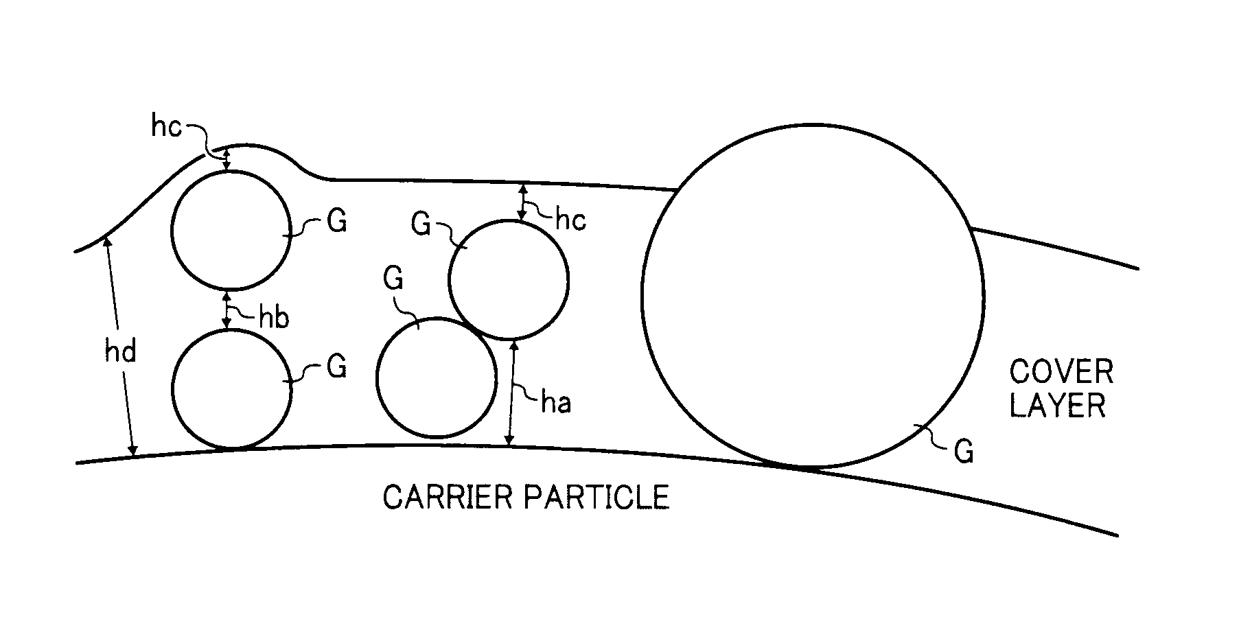
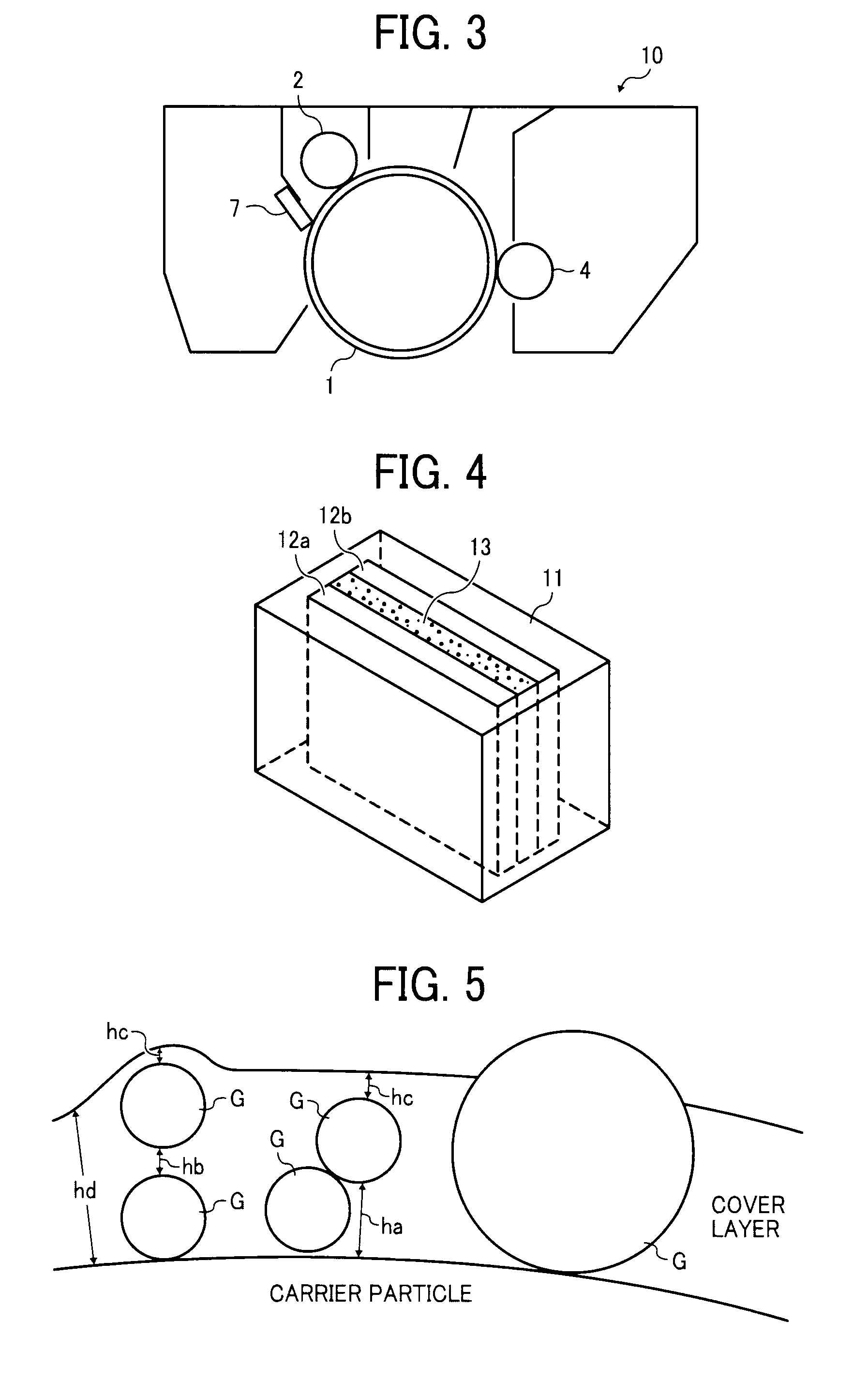
A carrier for use in a two component developer for developing an electrostatic latent image is provided. The carrier includes a particulate core material; and a cover layer located on a surface of the core material and including a silicone resin and barium sulfate. The cover layer includes Ba and Si at an atomic ratio of from 0.01 to 0.08 as determined by X-ray photoelectron spectroscopy.

Description

BACKGROUND OF THE INVENTION[0001]1. Field of the Invention[0002]The present invention relates to a carrier for use in a two component developer developing an electrostatic image, and to a two component developer using the carrier and a toner. In addition, the present invention also relates to a developing device, an image forming method, an image forming apparatus and a process cartridge using the two component developer.[0003]2. Description of the Related Art[0004]Electrophotographic image forming methods typically include the following processes:(1) Forming an electrostatic latent image on an image bearing member such as a photoreceptor (electrostatic latent image forming process);(2) Developing the electrostatic latent image with a developer including a toner to form a toner image on the image bearing member (developing process);(3) Transferring the toner image onto a recording material (transferring process); and(4) Fixing the toner image on the recording material, resulting in ...

Claims


Application Information

Patent Timeline
IPC IPC(8): G03G21/16G03G9/113G03G13/20G03G15/09
CPCG03G9/10G03G9/1136G03G13/08G03G13/06G03G9/1139
Inventor SAKATA, KOICHIMASUDA, MINORUNAKAJIMA, HISASHIYAMAGUCHI, KIMITOSHITAKAHASHI, YUTAKAIWATSUKI, HITOSHIYAMADA, SAORITANO, TOYOAKI
Owner RICOH KK
Why Eureka
Try Eureka