
Power Transmission for a Lawn Mower and a Lawn Mower Provided with Such a Transmission

a technology for lawn mowers and transmissions, which is applied in the direction of gearing, agriculture tools and machines, gearing, etc., can solve the problems of ad weight, complication of the system, and the inability to provide a reliable drive for small lawn mowers,

Inactive Publication Date: 2011-07-21
PERSSON LEIF
View PDF11 Cites 6 Cited by
  • Summary
  • Abstract
  • Description
  • Claims
  • Application Information

AI Technical Summary

Benefits of technology

[0011]Another object is to provide a transmission which will lead to cost and weight savings of a lawn mower by reducing the final drive system to one location in the transmission as opposed to one in each wheel.
[0013]This brings about a transmission to be used in a lawn mower that in a simple yet effective way can be vertically adjusted. The wheel axle can thus be driven by the lawn mower engine and without use of a special engine design for driving the transmission and without using sturdy height adjustment brackets.
[0014]According to a preferred embodiment the transmission is provided with an internal freewheeling device. This hinders rust and dirt from entering the system since a freewheeling system arranged within the transmission housing is not exposed to dirt as a freewheeling system arranged in proximity to the wheels.
[0015]An object of the present invention is also to provide a lawn mower with the wheels attached directly to the wheel axle of the transmission and where the transmission is powered by a simple belt and pulley design.
[0016]A further object is to provide a lawn mower which height can be adjusted in relation to a ground plane without affecting the parallelity between a vertical transmission axle and an engine crank shaft.
[0018]This makes it possible to use a simple belt drive transmission as opposed to a propeller shaft transmission.

Problems solved by technology

This can often lead to some complications due to rust and dirt entering the system.
This does not only ad weight, but also complication to the system.
The systems in use, where the drive axle is directly attached to the wheel typically utilize a very complicated drive system enabling the belt drive to be fixed.
The use of a car type differential does not provide a reliable drive on small lawn mowers unless operated on flat ground—due to large weight shifts on the driven wheels when operating on a slope.

Method used


Image

  • Power Transmission for a Lawn Mower and a Lawn Mower Provided with Such a Transmission
  • Power Transmission for a Lawn Mower and a Lawn Mower Provided with Such a Transmission
  • Power Transmission for a Lawn Mower and a Lawn Mower Provided with Such a Transmission

Examples


Embodiment Construction

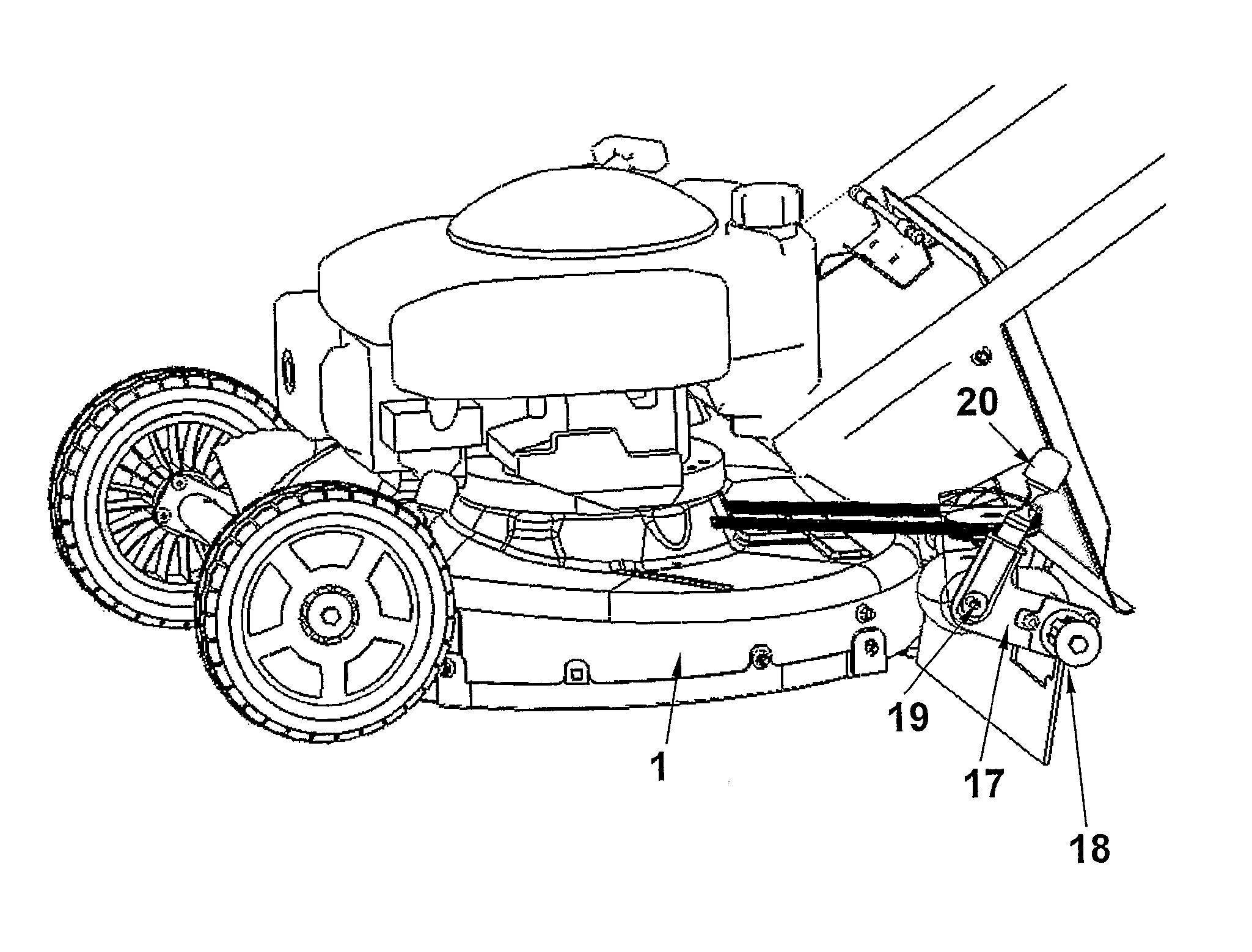
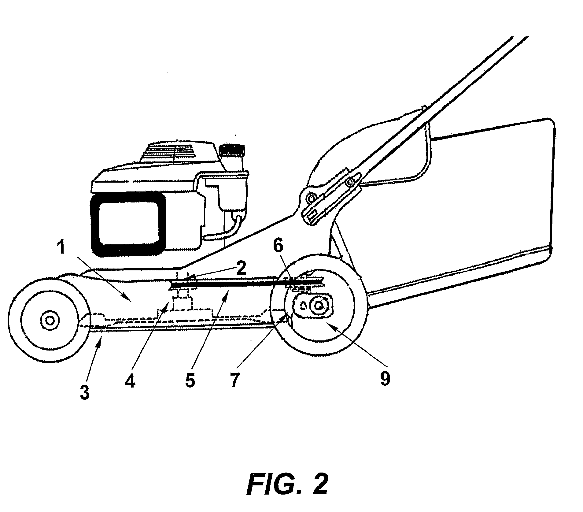
[0027]FIG. 2 shows a side view of a lawn mower equipped with a transmission according to an embodiment of the present invention. An engine, which can be any preferred known engine situated within a housing 1, is connected to a crank shaft 2, for rotation of the cutting blades 3. At the crank shaft 2, an engine pulley 4 is arranged for receiving a drive belt 5. The drive belt 5 connects the engine pulley 4 with a transmission pulley 6 arranged at a transmission / gear box 7. The transmission 7 is equipped with a hinge or an articulated joint or a pivot axle 11 which divides the transmission into two parts. The second part of the transmission is in turn connected to the wheel axle 9 running through the second transmission part.

[0028]FIG. 3 shows a cross section of a transmission according to a preferred embodiment of the present invention. A transmission axle 10 transfers the momentum from the transmission pulley. A pivot axle 11 located in the first part 7A of the transmission 7 forwar...


PUM


Abstract

The present invention concerns a power transmission for a rotary type of walk-behind lawn mower. The transmission comprises a first transmission part (7A) arranged to be mounted in a lawn mower housing (1) and comprising a transmission pulley (6) , which in turn is arranged to be connected to an engine pulley (4) of a lawn mower via a drive belt (5) . A second part (7B) of the transmission is arranged to be connected to a wheel axle (9) of the lawn mower, wherein the first transmission part (7A) is connected to the second transmission part (7B) via an articulated joint (11) such that the second transmission part (7B) and the wheel axle (9) are arranged to be pivotally mounted on said lawn mower housing (1) . Thereby pivoting will adjust the height of said lawn mower housing (1) in relation to a ground plane. The invention also concerns a walk-behind lawn mower comprising such a transmission.

Description

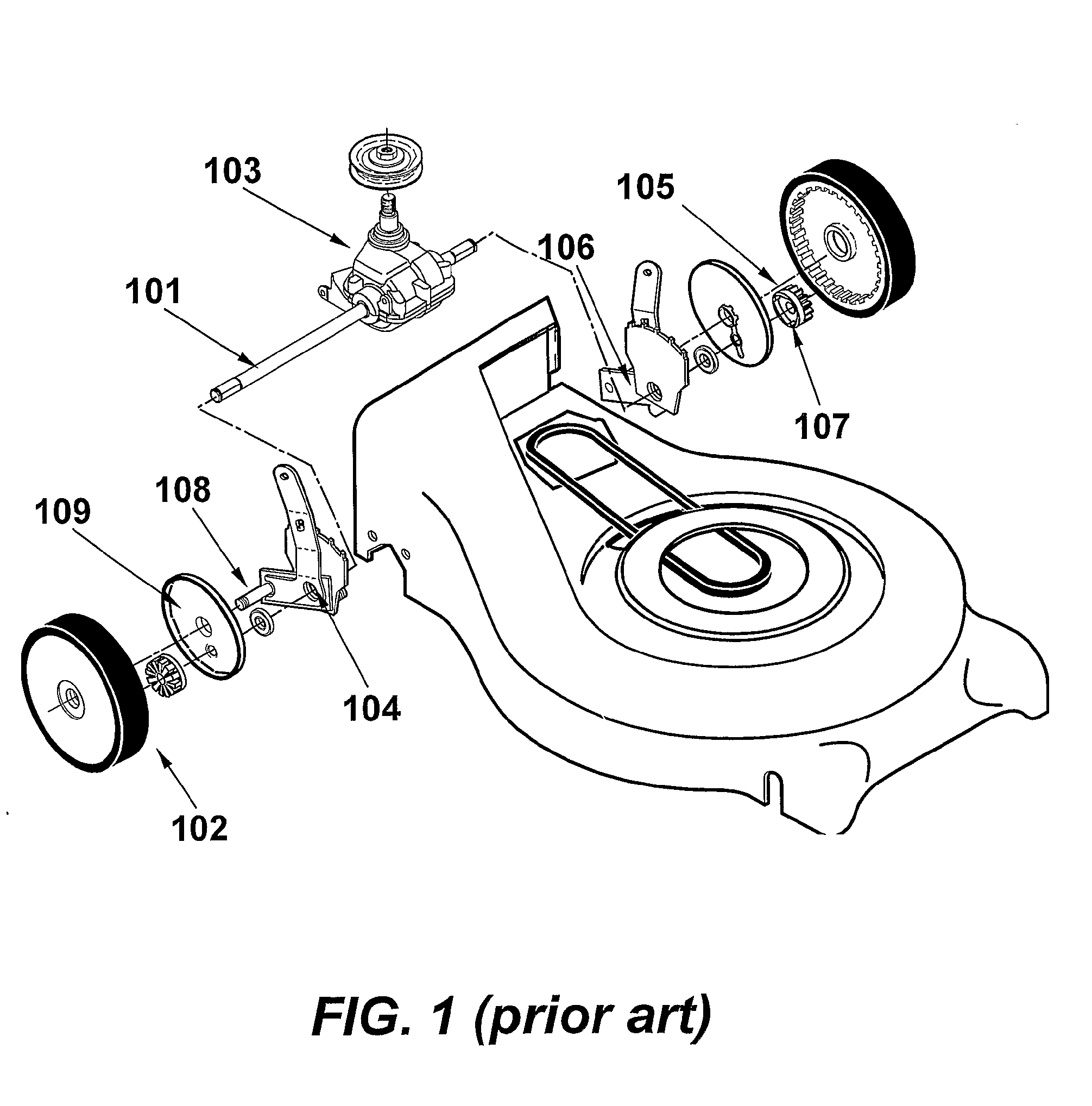
TECHNICAL FIELD[0001]The present invention concerns walk-behind rotary lawn mowers of dimensions typically less than 700 mm diameter and most commonly 480 to 530 mm diameter and equipped with a powered transmission that drives either the front or the rear wheels, and a transmission for such a lawn mower.BACKGROUND OF THE INVENTION[0002]The typical rotary lawnmower has a variable cutting height varying from 20 mm to as much as 100 mm.[0003]FIG. 1 shows a typical height adjustment mechanism in a lawn mower. The axle 101 that drives the wheels 102 is typically located at a fixed position on the mower deck. The drive axle 101 from the transmission 103 typically goes through the pivoting point 104 for the typical height adjustment pivoting system. To transmit the power from the transmission to the wheels the most common solution is to utilize a small gear 105 on the axle 101 that drives a gear in the wheel—for example on cogs on the inside parameter of the wheel.[0004]Another similar sol...

Claims


Application Information

Patent Timeline
IPC IPC(8): A01D43/00F16H7/02
CPCA01D34/74A01D2101/00A01D69/06
Inventor PERSSON, LEIF
Owner PERSSON LEIF
Learn More