Spiral heat exchanger

a heat exchanger and spiral technology, applied in the field of spiral heat exchangers, can solve the problems of overheating of electronic elements, constant increase of temperature between electronic devices and electronic elements, and high waste heat produced by electronic elements in these electronic devices, so as to increase heat exchange capacity, prolong heat exchange flow passages, and effectively upgrade the heat exchange efficiency of these effects

Inactive Publication Date: 2011-07-21
ASIA VITAL COMPONENTS SHENZHEN CO LTD
View PDF6 Cites 15 Cited by
  • Summary
  • Abstract
  • Description
  • Claims
  • Application Information

AI Technical Summary

Benefits of technology

[0016]To achieve the above and other objects, the spiral heat exchanger according to a preferred embodiment of the present invention mainly includes a first cover, a second cover, a spiral unit, and a driving unit. The first cover has at least one first inlet, at least one first outlet, and at least one first turbulence generating unit. The first inlet is a through hole arranged at a central area of the first cover, and the first outlet is a through hole arranged near an outer peripheral area of the first cover. The second cover is assembled to the first cover to define a chamber in between the first and the second cover. The second cover has at least one second inlet, at least one second outlet, and at least one second turbulence generating unit. The second inlet is a through hole arranged at a central area of the second cover, and the second outlet is also a through hole arranged near an outer peripheral area of the second cover. The spiral unit is arranged in the chamber and includes a first and a second spiral member. The first spiral member is spirally extended from the first inlet in a radially outward direction to the first outlet to form a first flow passage communicating with the first inlet and the first outlet, and the second spiral member is s

Problems solved by technology

However, electronic elements in these electronic devices will produce high amount of waste heat when they operate at high speed.
The waste heat, if not timely removed, tends to accumulate in the electronic devices and results in constantly raised temperature in the electronic devices and the electronic element thereof.
In worse conditions, the accumulated waste heat will cause overheat of the electronic elements and accordingly, failure, damage, or lowered operating efficiency thereof.
Further, the plate-type heat exchanger 1 provides only one-way flow passages 14 and limited heat exchange area, and therefore has apparently low heat exchange efficiency and low heat transfer effect.
Accordingly, the heat dissipation effect provided by the plate-typ

Method used


Image

  • Spiral heat exchanger
  • Spiral heat exchanger
  • Spiral heat exchanger

Examples


Embodiment Construction

[0030]The present invention will now be described with some preferred embodiments thereof. For the purpose of easy to understand, elements that are the same in the preferred embodiments are denoted by the same reference numerals.

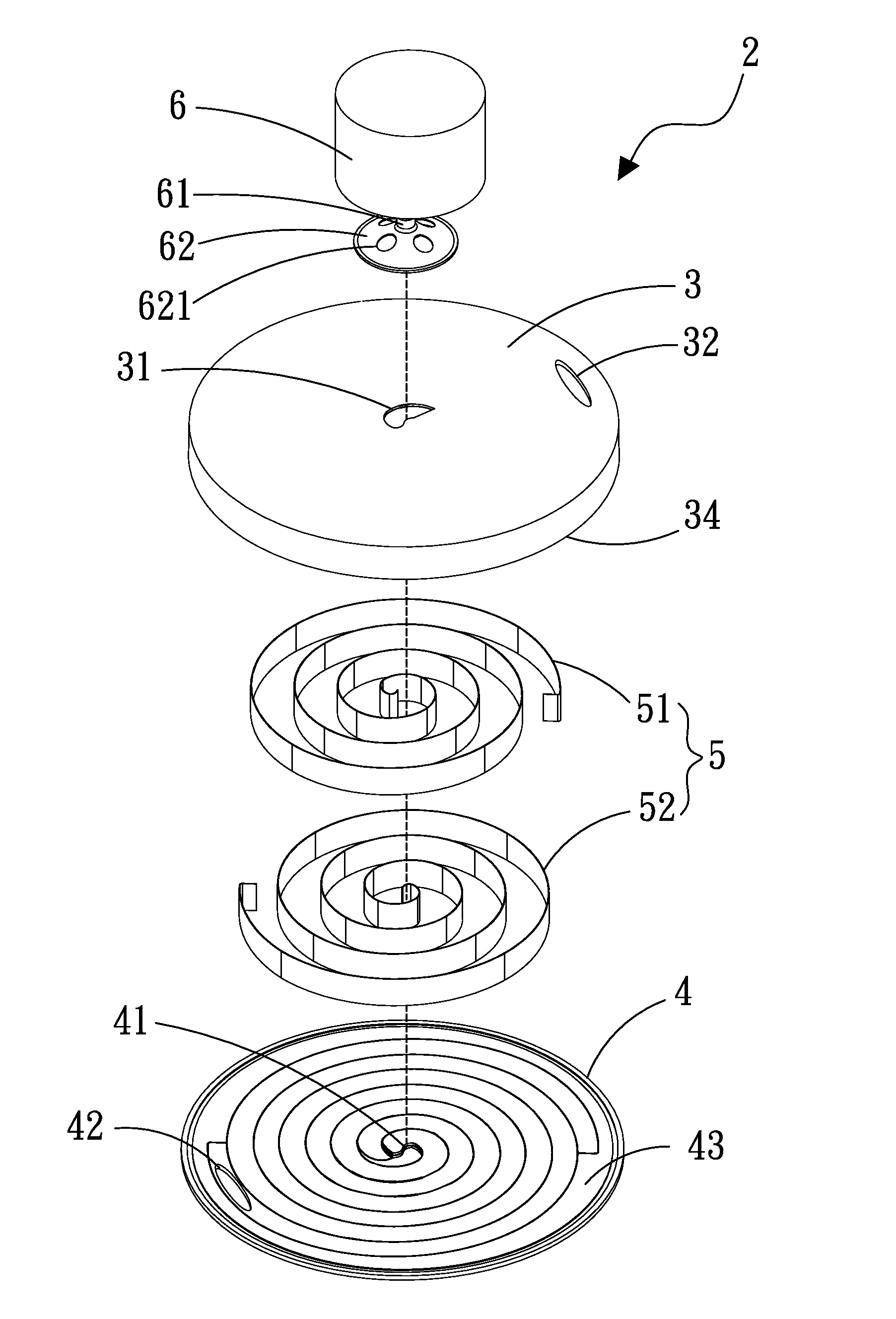
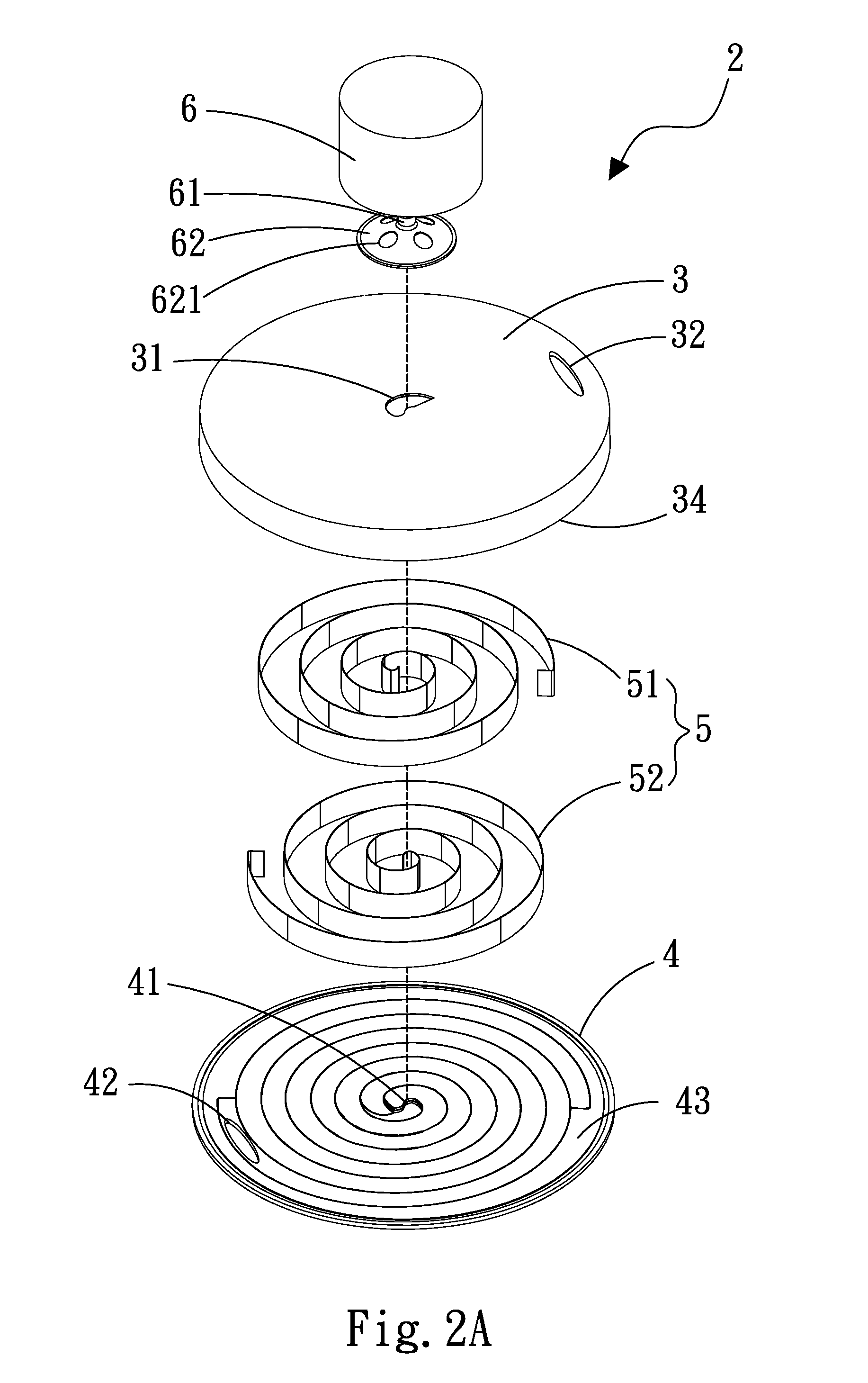
[0031]Please refer to FIGS. 2A, 2B to 5. A spiral heat exchanger 2 according to a first preferred embodiment of the present invention includes a first cover 3, a second cover 4, a spiral unit 5, and a driving unit 6. The first cover 3 is provided with at least one first inlet 31, at least one first outlet 32, and a first inner face 33. The first inlet 31 is a through hole arranged at a central area of the first cover 3, and the first outlet 32 is also a through hole arranged near an outer peripheral area of the first cover 3. The second cover 4 is assembled to the first cover 3 to define a chamber 34 in between the first and the second cover 3, 4. The second cover 4 is provided with at least one second inlet 41, at least one second outlet 42, and a second in...


PUM


Abstract

A spiral heat exchanger includes two assembled covers defining a chamber therebetween for receiving a spiral unit therein. The spiral unit includes a first and a second spiral member separately spirally extending from a central outlet to a peripheral outlet on the two covers to respectively form a first and a second flow passage. A driving unit is assembled to and drives the assembled covers to rotate at the same time, so that cold and hot airflows respectively enter and flow through the first and second spiral members from the central outlet to the peripheral outlet under a centrifugal force to exchange heat at the spiral unit. The spiral unit provides extended flow passages and increased heat exchange area, giving the spiral heat exchanger increased heat transfer capacity and heat exchange efficiency and allowing omission of fans and radiating fin assembly to eliminate operating noise and accumulated dust.

Description

[0001]This application claims the priority benefit of Taiwan patent application number 099101501 filed on Jan. 20, 2010.FIELD OF THE INVENTION[0002]The present invention relates to a heat exchanger, and more particularly to a spiral heat exchanger that includes an internal spiral unit to provided effectively extended heat exchange flow passages, and, when being driven to rotate, uses a centrifugal force to establish a flow field of cold and hot fluids in the heat exchanger without the need of using a conventional thermal module with fan and radiating fin assembly, and can accordingly, avoid the problems of noise caused by rotating fan blades and accumulated dust in the radiating fin assembly.BACKGROUND OF THE INVENTION[0003]Thanks to the constant progress in the electronic information technologies, various kinds of electronic devices, such as desktop computers, notebook computers, communication chesses, electric home appliances, industrial electronic apparatus, etc., have become hig...

Claims


Application Information

Patent Timeline
IPC IPC(8): F28D7/02
CPCF28D11/02F28D7/04
Inventor CHANG, SHYY-WOEICHIANG, KUEI-FENG
Owner ASIA VITAL COMPONENTS SHENZHEN CO LTD
Why Eureka
Try Eureka