Compact Electromagnetic Plasma Ignition Device

a plasma ignition device and electromagnetic technology, applied in the direction of sparking plugs, machines/engines, corona discharge, etc., can solve the problems of consuming a limited fossil fuel supply, reducing the overall ignition efficiency, and becoming more difficult to ignite and combust, so as to reduce the amount of aperture radiation, reduce the geometry of the aperture, and high efficiency

Active Publication Date: 2011-07-21
WEST VIRGINIA UNIVERSITY
View PDF36 Cites 32 Cited by
  • Summary
  • Abstract
  • Description
  • Claims
  • Application Information

AI Technical Summary

Benefits of technology

[0010]The present disclosure meets the above and other needs. A quarter wave coaxial cavity resonator (QWCCR) is adapted to operate in the next generation of lean high efficiency internal combustion engines. In embodiments, the QWCCR comprises a folded cavity that permits the use of lower operating frequencies than an unfolded cavity of comparable length. In embodiments, the QWCCR comprises a

Problems solved by technology

Today a very large number of spark ignited (SI) engines are in use, consuming a limited fossil fuel supply.
Unfortunately, as mixtures are leaned, they become more difficult to ignite and combust.
As more energetic sparks are used, their overall ignition efficiency is reduced because the higher energy levels are detrimental to the spark plug lifetime.
These higher energy levels also contribute to the formation of undesirable pollutants.
When the corona discharge plasma is used as an ignition source for a combustion chamber, a reduction in the amount or strength of the corona discharge plasma is undesirable as it could result in non-ignition of combustible materials in the combustion chamber.
However, in practice, the resonant frequency of a quarter wave coaxial cavity resonator m

Method used


Image

  • Compact Electromagnetic Plasma Ignition Device
  • Compact Electromagnetic Plasma Ignition Device
  • Compact Electromagnetic Plasma Ignition Device

Examples


Embodiment Construction

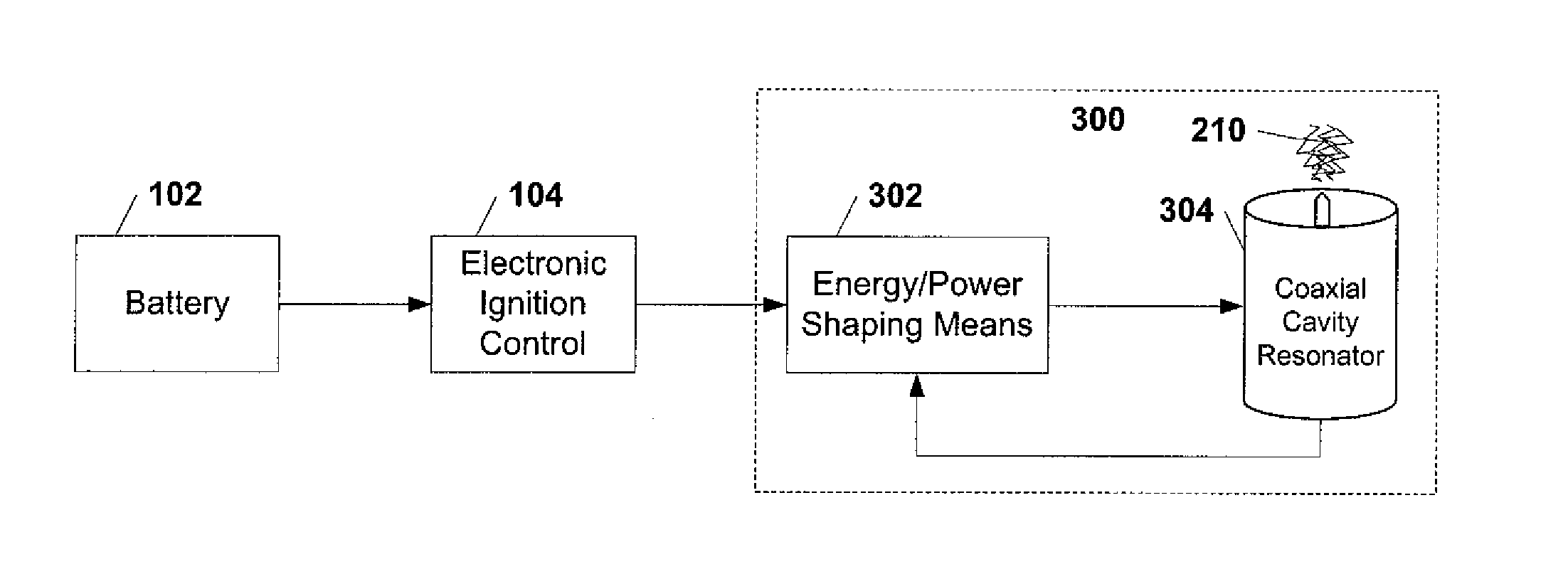
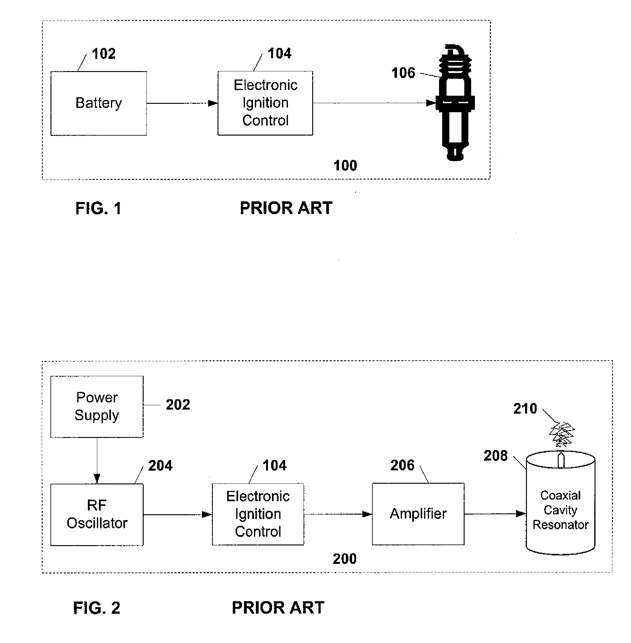
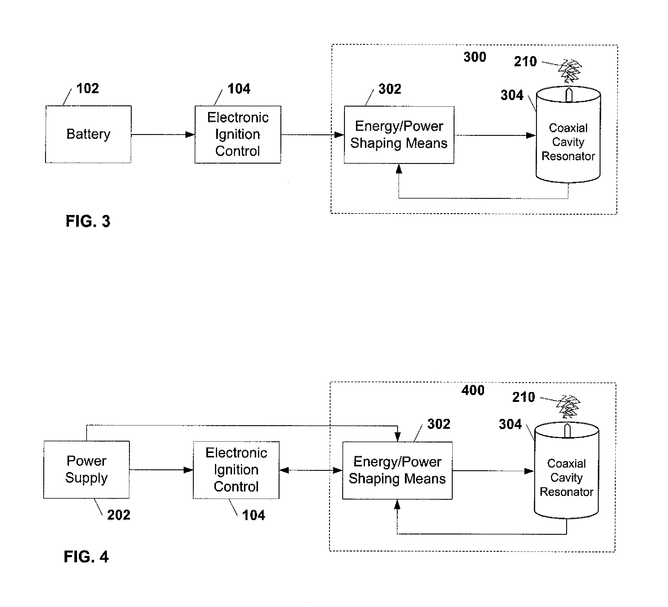
[0038]FIG. 1 and FIG. 2 detail the prior art ignition systems. Exemplary embodiments of the present invention are detailed in FIGS. 3-25.

[0039]Prior Art Ignition System with a Spark Plug

[0040]Referring now to the schematic diagram of a prior art ignition system 100 depicted in FIG. 1, a battery 102 connects to an electronic ignition control system 104 which is connected by a spark plug wire to the terminal end of a spark plug 106.

[0041]In a typical prior art ignition system 100, like that found in an automobile, a battery 102 provides electrical power to an electronic ignition control system 104. The electronic ignition control system 104 determines the proper timing for triggering an ignition event, and at the appropriate time sends a high voltage pulse via a spark plug wire to the terminal end of a spark plug 106. The high voltage pulse causes a spark to discharge at the tip of the spark plug 106 that is displaced inside of a combustion chamber (not shown). The spark ignites combu...


PUM


Abstract

A quarter wave coaxial cavity resonator for producing corona discharge plasma from is presented. The quarter wave coaxial cavity resonator has a folded cavity made of opposing concentric cavity members that are nested together to form a continuous cavity ending in a aperture. A center conductor with a tip is positioned in the cavity. The folded cavity advantageously permits the coaxial cavity resonator to resonate at a lower operating frequency than an unfolded quarter wave coaxial cavity resonator of the same length. Embodiments of the quarter wave coaxial cavity resonator use narrower apertures to reduce radiative losses, and include center conductors that are reactive load elements, such as helical coils. When a radio frequency (RF) oscillation is produced in the quarter wave coaxial cavity resonator, corona discharge plasma is formed at the tip of the center conductor. The corona discharge plasma can be used to ignite combustible materials in combustion chambers of combustion engines.

Description

CROSS-REFERENCE TO RELATED APPLICATIONS[0001]The present application is a continuation-in-part of U.S. patent application Ser. No. 12 / 023,770 filed Jan. 31, 2008, entitled “Plasma Generating Ignition System and Associated Method”, and is related to U.S. patent application Ser. No. 12 / 721,231 filed Mar. 10, 2010, entitled “Quarter Wave Coaxial Cavity Igniter for Combustion Engines”, the disclosures of which are incorporated herein by reference in their entirety.TECHNICAL FIELD[0002]Embodiments of the present disclosure relate generally to systems, devices, and methods for using a quarter wave coaxial cavity resonator as an ignition source for a combustion engine.BACKGROUND OF THE INVENTION[0003]There are two basic methods used to ignite combustion mixtures. Auto ignition through compression and spark ignition. Today a very large number of spark ignited (SI) engines are in use, consuming a limited fossil fuel supply. A significant environmental and economic benefit is obtained by maki...

Claims


Application Information

Patent Timeline
IPC IPC(8): H01P7/04
CPCF02P9/007H01J37/32091H01T13/50F02P23/045F02P3/01H01T9/00H01T19/00
Inventor SMITH, JAMES E.PERTL, FRANZ A.
Owner WEST VIRGINIA UNIVERSITY
Why Eureka
Try Eureka