Optical spectral filter, angular filter and polariser

a technology of optical spectral filter and polariser, applied in the direction of layered products, instruments, lamination, etc., can solve the problems of only narrow bandwidth, unwanted diffraction effects, and add to the size and complexity of the devi

Active Publication Date: 2011-07-21
STREAM TECH
View PDF4 Cites 20 Cited by
  • Summary
  • Abstract
  • Description
  • Claims
  • Application Information

AI Technical Summary

Benefits of technology

[0013]Several embodiments of the devices described here allow the transmission wavelength(s) to be tuned. Such a capability is potentially useful for applications that require the excitation wavelength to be changed in order, for example, t

Problems solved by technology

This adds to the size and complexity of the device because achieving a high degree of angular filtering requires a long optical path.
Hard apertures also cause unwanted diffraction effects.
The peak transmission wavelength of these devices can cover a wide range, but for a given range the bandwidth can only be narrow if the size of the device is large.
Another drawback for some applications is that the

Method used


Image

  • Optical spectral filter, angular filter and polariser
  • Optical spectral filter, angular filter and polariser
  • Optical spectral filter, angular filter and polariser

Examples


first embodiment

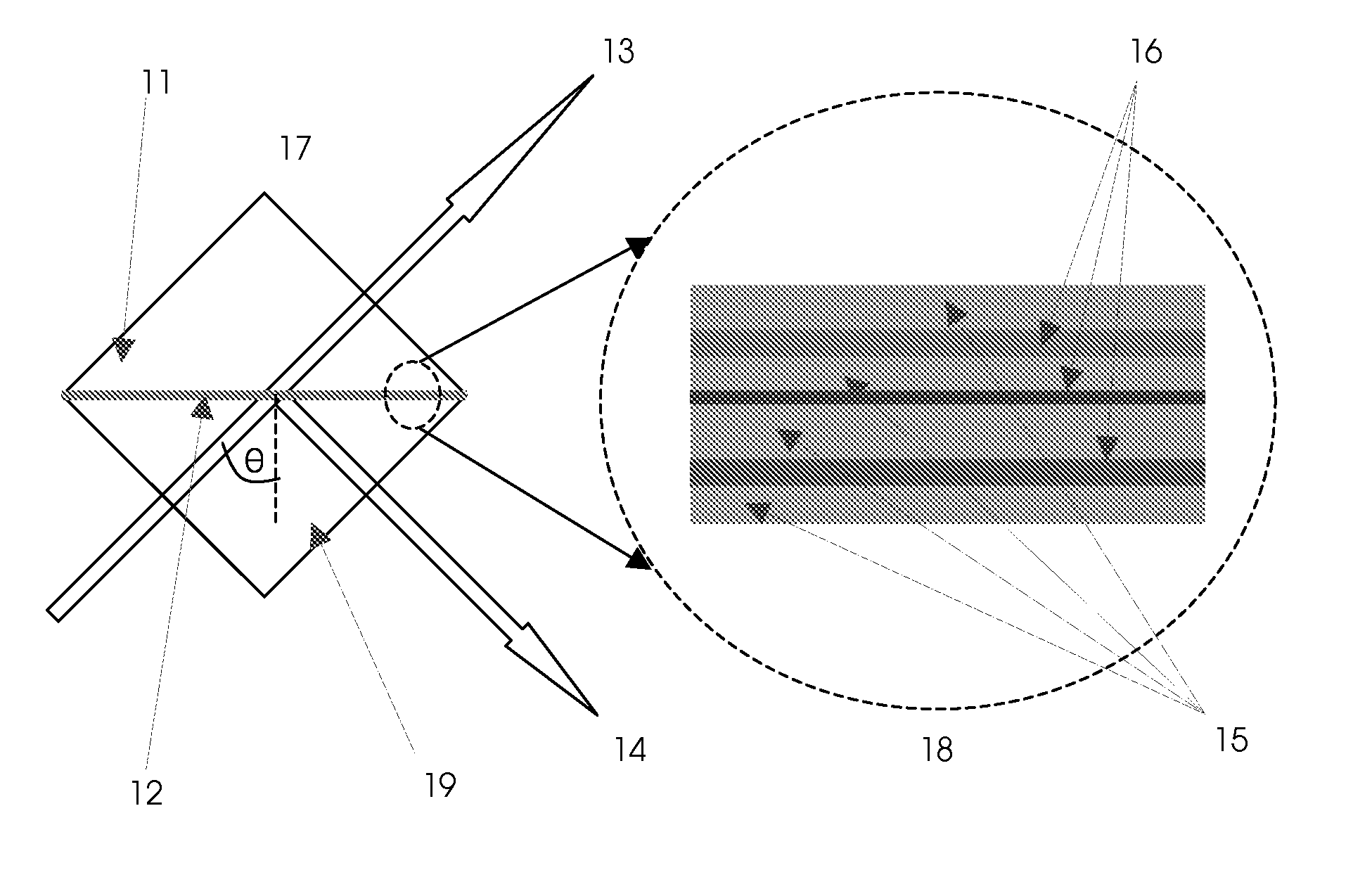
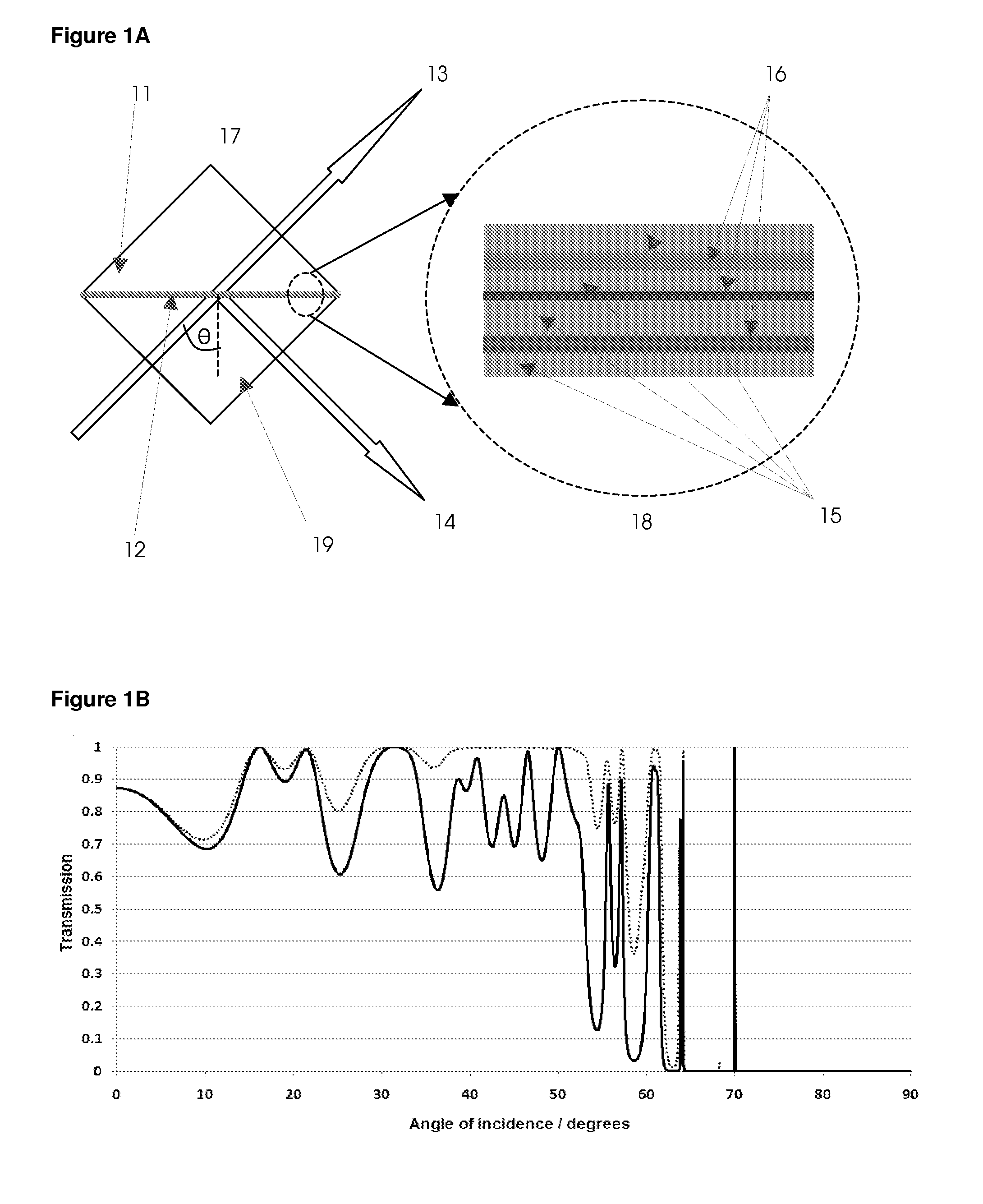
[0060]In the first embodiment, there is provided a filter for spectrally filtering, polarising and for some embodiments also angularly filtering input light. The relevant figures are FIG. 1A, FIG. 1B and FIG. 1C.

[0061]The structure comprises:

[0062]Input prism 19, assumed to be of an isotropic material, with refractive index 1.52

[0063]First layer, adjacent to the input prism, assumed to be of an isotropic material, with refractive index 1.38, and thickness 0.55 microns

[0064]Second layer, adjacent to the first layer, assumed to be of an isotropic material, with refractive index 1.85, and thickness 0.03335 microns

[0065]Third layer, adjacent to the second layer, assumed to be of an isotropic material, with refractive index 1.38, and thickness 1.1 microns

[0066]Fourth layer, adjacent to the first layer, assumed to be of an isotropic material, with refractive index 1.75, and thickness 0.44517 microns

[0067]Fifth layer, adjacent to the first layer, assumed to be of an isotropic material, wit...

second embodiment

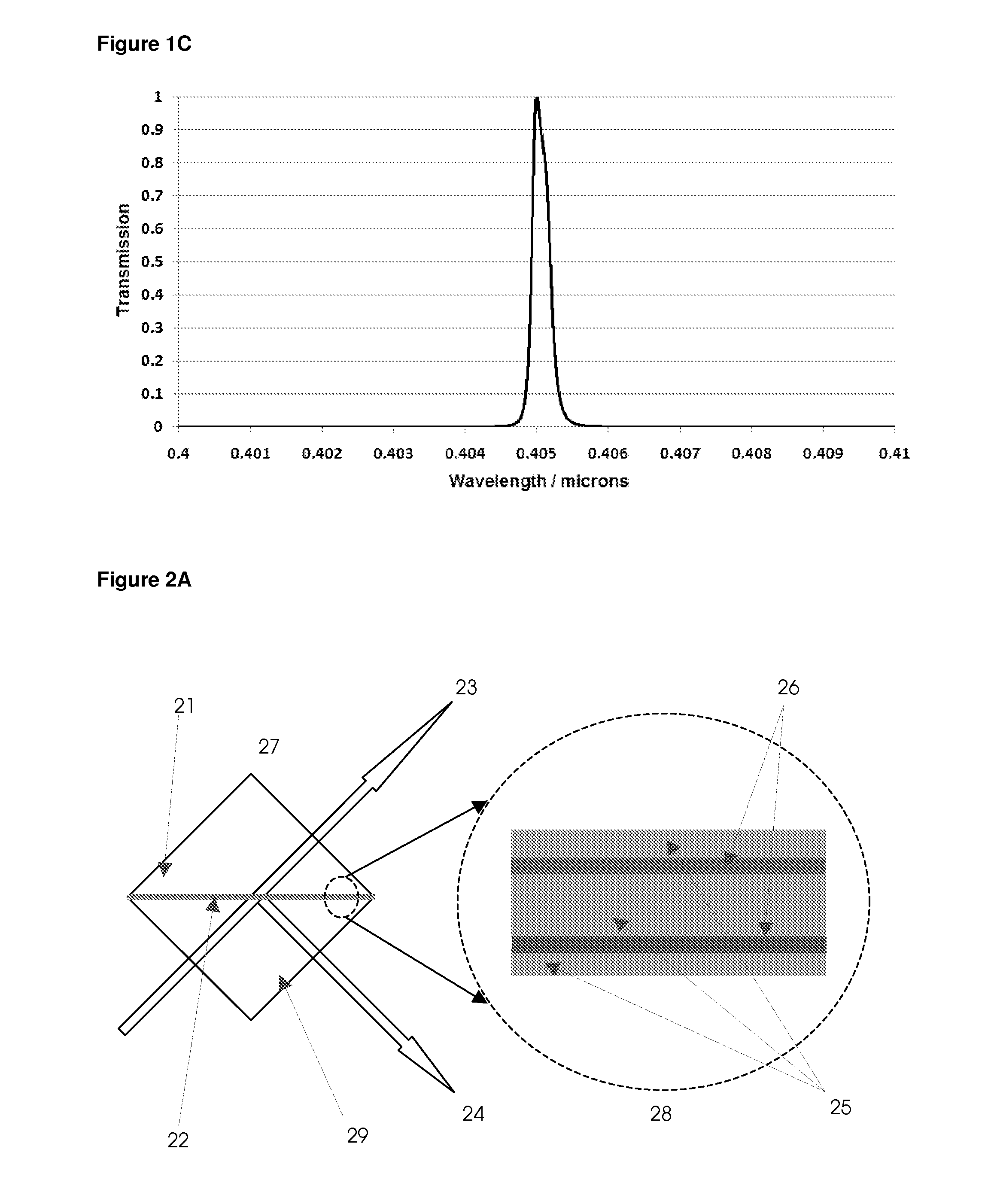
[0075]In the second embodiment, there is provided a filter for spectrally filtering, polarising and angularly filtering input light. The relevant figures are FIG. 2A, FIG. 2B, FIG. 2C, and FIG. 2D.

[0076]The structure comprises:

[0077]Input prism 29, assumed to be of an isotropic material, with refractive index 1.52

[0078]First layer, adjacent to the input prism, assumed to be of an isotropic material, with refractive index 1.38, and thickness 0.5 microns

[0079]Second layer, adjacent to the first layer, assumed to be of an isotropic material, with refractive index 1.85, and thickness 0.03336 microns

[0080]Third layer, adjacent to the second layer, assumed to be of an isotropic material, with refractive index 1.38, and thickness 1 micron

[0081]Fourth layer, adjacent to the third layer, assumed to be of an isotropic material, with refractive index 1.65, and thickness 0.31062 microns

[0082]Fifth layer, adjacent to the fourth layer, assumed to be of an isotropic material, with refractive index...

third embodiment

[0093]In the third embodiment, there is provided a filter for spectrally filtering, polarising and angularly filtering input light. A demonstration filter corresponding to this embodiment has been fabricated using methods below and tested. Results will be presented below. The relevant figures are FIG. 3A, FIG. 3B and FIG. 3C.

[0094]The structure depicted here is:

[0095]Input prism 39, assumed to be of an isotropic material, with refractive index 1.52

[0096]First layer, adjacent to the input prism, assumed to be of an isotropic material, with refractive index 1.38, and thickness 0.5 microns

[0097]Second layer, adjacent to the first layer, assumed to be of an isotropic material, with refractive index 1.65, and thickness 0.0656 microns

[0098]Third layer, adjacent to the second layer, assumed to be of an isotropic material, with refractive index 1.38, and thickness 1 micron

[0099]Fourth layer, adjacent to the third layer, assumed to be of an isotropic material, with refractive index 1.65, and...


PUM

PropertyMeasurementUnit
Angleaaaaaaaaaa
Wavelengthaaaaaaaaaa

Abstract

A filter and fabrication process for a thin film filter that is based on frustrated total internal reflection and multiple waveguide layers, in which the waveguide modes are resonantly coupled. The physics of the design is related to prism coupling of light into planar waveguides, and waveguide coupling between planar waveguides in close proximity. Embodiments include a filter that acts as a bandpass filter and polarizer, a filter that acts as a bandpass filter, polarizer and angle filter (spatial filter), a filter that is widely tunable, and a filter that is widely tunable in both peak transmission wavelength and width. Methods of fabrication are disclosed, and methods to correct for manufacturing errors in thin film deposition are described. The filter embodiments can also be used in reflection as notch filters in wavelength and angle, for a particular polarization component.

Description

FIELD OF THE INVENTION[0001]This invention relates to an apparatus and method for spectrally filtering and polarising a beam of light.BACKGROUND OF THE INVENTION[0002]Optical filters are fundamental elements in many optical instruments and setups. In many optical techniques, such as but not limited to, fluorescence spectroscopy, fluorescence anisotropy and Raman spectroscopy, it is important that the excitation light be spectrally distinct from that spectral portion of the fluorescence light that is used for detection. Optical filters that exploit thin-film interference effects to spectrally filter the light are commonly used to filter the excitation light and the fluorescence light.[0003]Linear polarisers are optical elements that, ideally, only transmit one component of the input electromagnetic radiation, where the component of the electric field that is transmitted is oriented parallel to the axis of the polariser.[0004]In addition to these two properties, may also be desirable ...

Claims


Application Information

Patent Timeline
IPC IPC(8): G02B6/26B32B37/02
CPCG02B5/285G02F1/0102G02B27/283G02B6/105
Inventor SINGH, KIRATPRENNER, ELMARSTREATER, ALAN D.
Owner STREAM TECH
Why Eureka
Try Eureka