Safety input device
- Summary
- Abstract
- Description
- Claims
- Application Information
AI Technical Summary
Benefits of technology
Problems solved by technology
Method used
Image

Examples
first embodiment
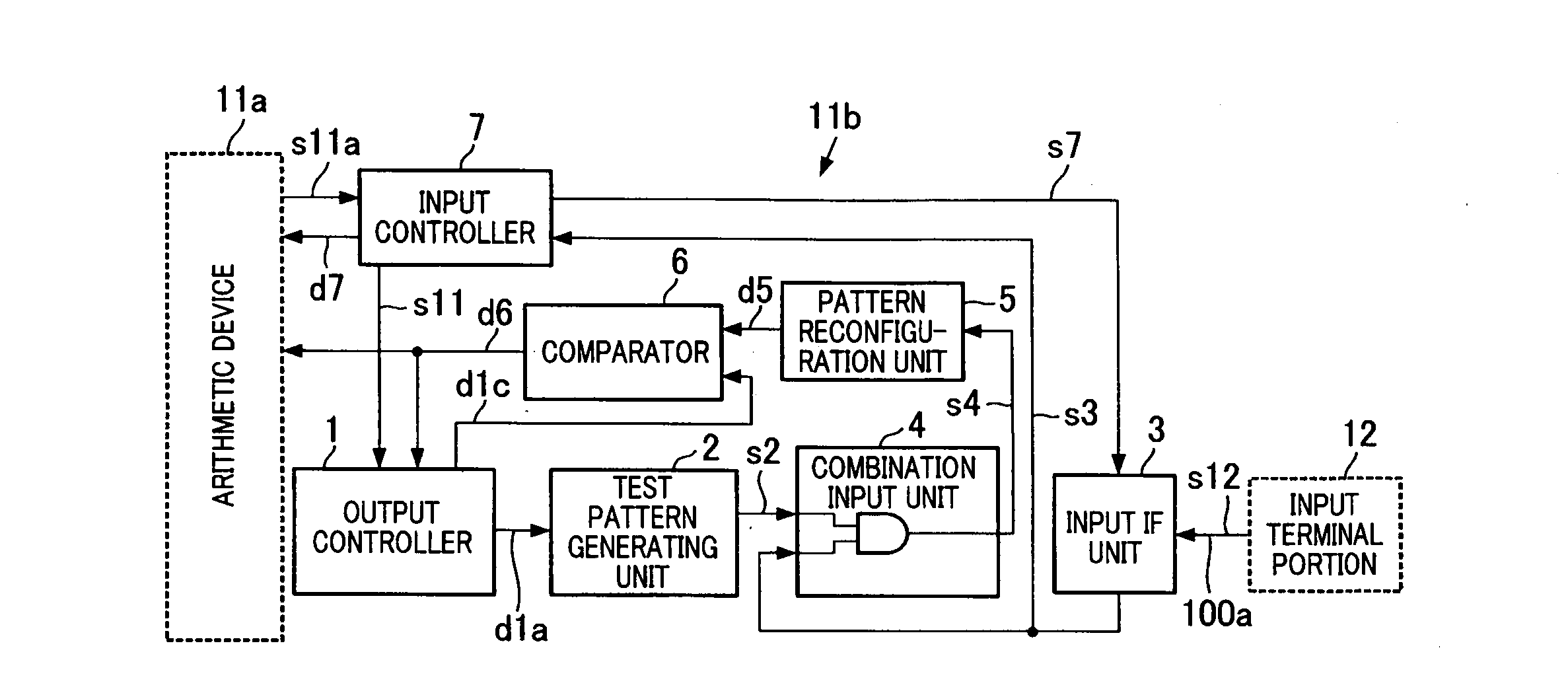
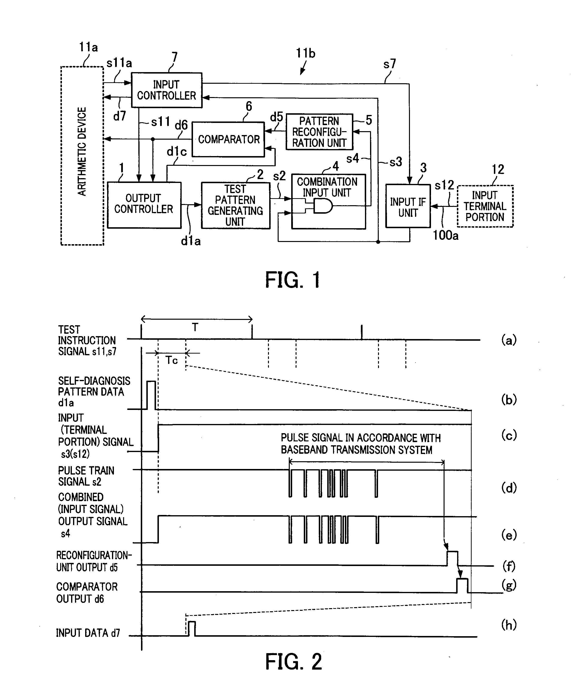
A safety input device according to a first embodiment of the invention will be described with reference to FIGS. 1 and 2.
Concerning a safety control system employing the safety input device, the same units as those of the configuration described in FIG. 5 will be designated by the same reference numerals, and description of those units will be omitted herein. To distinguish the safety input device of the invention from the conventional input device 11b described in FIG. 5, the safety input device of the invention will be hereinafter referred to as a safety output device 11b.
In FIG. 1, the safety input device 11b of the invention is provided to a control device and is configured to convert an input signal sent from an input terminal portion 12, such as a sensor, into input data and to send the input data to an arithmetic device 11a. The safety input device 11b is also configured to perform a self-diagnosis.
The safety input device 11b includes an input controller 7, an output control...
second embodiment
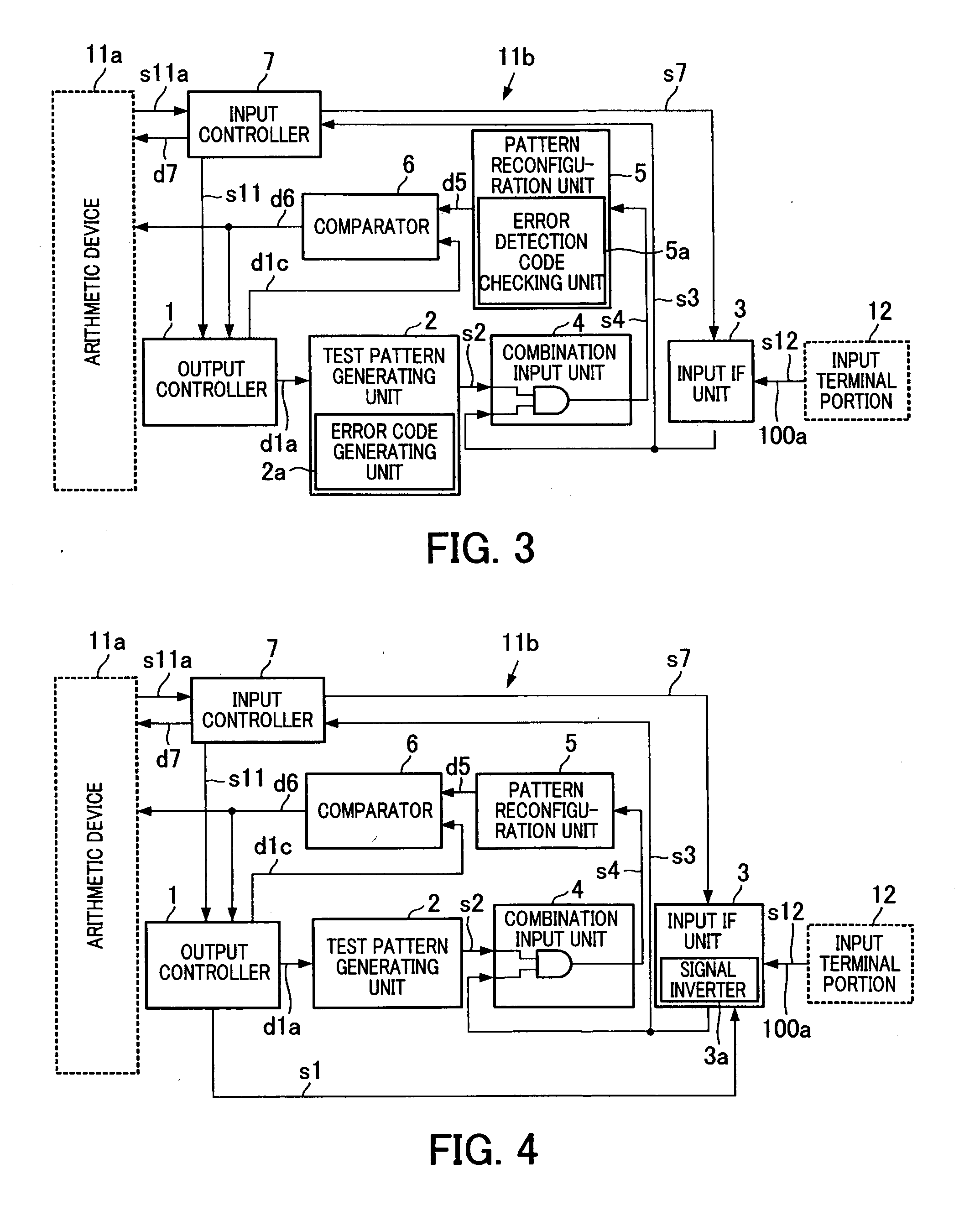
Next, a safety input device 11b according to a second embodiment will be described with reference to FIG. 3. Portions in the second embodiment which are the same as those shown in FIG. 1 will be designated by the same reference numerals, and description of those portions will be omitted.
The second embodiment is different from the first embodiment in the following respects. Specifically, in the first embodiment, the test pattern generating unit 2 generates only the self-diagnosis pattern data. In contrast, in the second embodiment, the test pattern generating unit 2 is provided with an error code generating unit 2a to attach an error detection code to the self-diagnosis pattern data. Moreover, the pattern reconfiguration unit 5 is provided with an error detection code checking unit 5a configured to check the error detection code thus attached.
Moreover, the second embodiment is also different in that the comparator 6 is configured to compare the preset self-diagnosis pattern data with...
third embodiment
Next, a safety output device according to a third embodiment will be described with reference to FIG. 4. Portions in the third embodiment which are the same as the portions shown in FIG. 1 will be designated by the same reference numerals, and description of those portions will be omitted.
The third embodiment is different from the first embodiment in the following respects. Specifically, the input interface unit 3 includes a signal inverter 3a that inverts the input signal s3 when the output controller 1 does not instruct output of the self-diagnosis pattern data. Meanwhile, the comparator 6 is configured to make a comparison using the inverted data while considering a timing of an input inversion instruction signal s1 for the input signal, instructed by the output controller.
Specifically, the diagnosis using the self-diagnosis pattern data according to the configuration of the first embodiment has a problem when the signal cannot be outputted at the 0 V potential due to disconnecti...
PUM
 Abstract
Description
Claims
Application Information
 - R&D
- Intellectual Property
- Life Sciences
- Materials
- Tech Scout
- Unparalleled Data Quality
- Higher Quality Content
- 60% Fewer Hallucinations
Browse by: Latest US Patents, China's latest patents, Technical Efficacy Thesaurus, Application Domain, Technology Topic, Popular Technical Reports.
© 2025 PatSnap. All rights reserved.Legal|Privacy policy|Modern Slavery Act Transparency Statement|Sitemap|About US| Contact US: help@patsnap.com