Exhaust system for a lean burn IC engine

Inactive Publication Date: 2011-07-28
JOHNSON MATTHEY PLC
View PDF10 Cites 47 Cited by
  • Summary
  • Abstract
  • Description
  • Claims
  • Application Information

AI Technical Summary

Benefits of technology

[0020]Suitable coating formulations, typically referred to as “washcoats”, are designed to avoid or reduce pore blockage either at the wall surface or interconnecting between pores within wall structure. As a result, catalyst, e.g. SCR catalyst, introduced into the channels from one end of a wall-flow filter using zone-coating techniques available to those skilled in the art (see for example EP 1064094), may move through the pore structure of the filter to sit within pores of the wall structure or even to emerge at the surface of the channels of the opposite

Problems solved by technology

A problem with the wall-flow filter disclosed in DE 10 2005 005 663 A1 is that it can lead to increased emissions of ammonia following NAC regen

Method used


Image

  • Exhaust system for a lean burn IC engine
  • Exhaust system for a lean burn IC engine
  • Exhaust system for a lean burn IC engine

Examples


first embodiment

[0041]In a first embodiment, the clean-up catalyst is disposed in a separate layer overlying the SCR catalyst, wherein the SCR catalyst is present as a separate coating on the wall-flow filter or the SCR catalyst is integral to the wall-flow filter, e.g. either the SCR catalyst is impregnated as a salt solution into the material of a virgin wall-flow filter, or SCR catalyst is combined with ingredients that form a structure of the substrate monolith that is then extruded into a flow-through monolith and, following drying and calcination, alternate ends of the channels are blocked in a chequer board pattern arrangement at one end of the substrate monolith and unblocked channels are alternately blocked at the opposite end thereof in a similar arrangement.

second embodiment

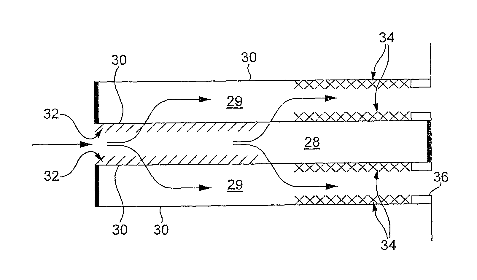
[0042]According to the second aspect of the invention, the wall-flow filter comprises a length extending from a first end to a second end, wherein the NAC is located in a first zone of substantially uniform length from 30-70% of the wall-flow filter length with an upstream zone end defined by the first end of the wall-flow filter, the SCR catalyst is located in a second zone of substantially uniform length from 30-65% of the wall-flow filter length with an upstream end of the second zone defined by a downstream end of the first zone and the clean-up catalyst is disposed in a third zone of substantially uniform length from 5-40% of the wall-flow filter length with an upstream end of the third zone defined by a downstream end of the second zone and at a downstream end by the second end of the wall-flow filter.

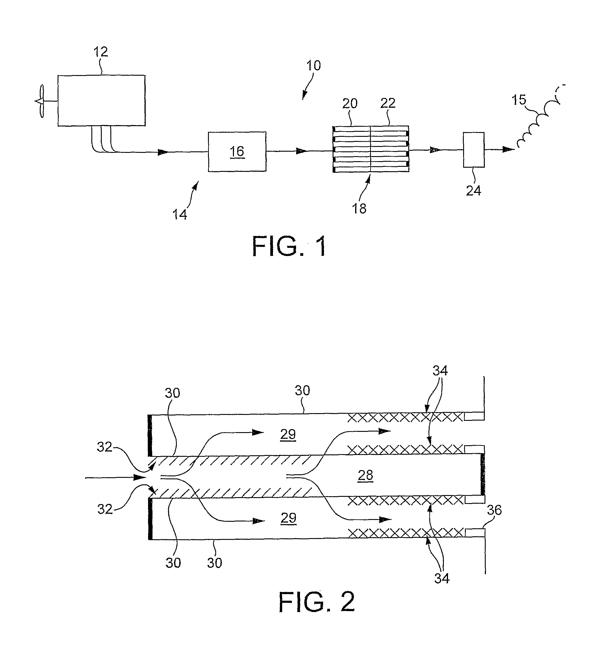
[0043]The exhaust system can be used to treat emissions from a lean-burn internal combustion engine, particularly of a vehicle, including lean-burn gasoline and diesel applicatio...


PUM

PropertyMeasurementUnit
Fractionaaaaaaaaaa
Fractionaaaaaaaaaa
Fractionaaaaaaaaaa

Abstract

An exhaust system(10) for a lean-burn internal combustion engine (12) comprises a first substrate monolith (16) comprising a catalyst for oxidising nitric oxide (NO) comprising a catalytic oxidation component followed downstream by a second substrate monolith (18) which is a wall-flow filter having inlet channels and outlet channels, wherein the inlet channels comprise a NO x absorber catalyst (20) and the outlet channels comprise a catalyst for selective catalytic reduction (22) of nitrogen oxides with nitrogenous reductant.

Description

CROSS-REFERENCE TO RELATED APPLICATIONS[0001]This application is the U.S. National Phase application of PCT International Application No. PCT / GB2009 / 050794, filed Jul. 6, 2009, and claims priority of British Patent Application No. 0812544.5, filed Jul. 9, 2008, the disclosures of both of which are incorporated herein by reference in their entirety for all purposes.FIELD OF THE INVENTION[0002]The present invention relates to an exhaust system for a lean-burn internal combustion engine, more especially for diesel (compression ignition) engine, which system comprising a NOx absorber catalyst (NAC) and a catalyst for selective catalytic reduction (SCR) of nitrogen oxides (NOx) using a nitrogenous reductant.BACKGROUND OF THE INVENTION[0003]NOx absorber catalyst (NAC) are known e.g. from U.S. Pat. No. 5,473,887 (the entire contents of which is incorporated herein by reference) and are designed to adsorb nitrogen oxides (NOx) from lean exhaust gas (lambda>1) and to desorb the NOx when t...

Claims


Application Information

Patent Timeline
IPC IPC(8): F01N3/035F01N3/10
CPCF01N3/0222B01D2255/50F01N3/035F01N3/0814F01N3/0821F01N3/0842F01N3/10F01N3/2073F01N3/28F01N2240/18F01N2240/25F01N2250/02F01N2250/12F01N2250/14F01N2510/0682F01N2570/10F01N2570/12F01N2570/14F01N2570/18Y02T10/24B01D2255/2063B01D2255/204B01D2255/202B01D2255/106B01D2255/1021B01D2255/207B01D53/94B01D2255/2092B01D2255/20761B01D2255/20738B01D2255/20723F01N3/0231Y02T10/12Y02A50/20F01N3/022F01N3/023F01N3/20
Inventor CHANDLER, GUY RICHARDCOLLINS, NEIL ROBERTPHILLIPS, PAUL RICHARDSWALLOW, DANIEL
Owner JOHNSON MATTHEY PLC
Why Eureka
Try Eureka