Capacitive humidity detector with nanoporous hydrophilic dielectric

a humidity detector and nanoporous technology, applied in the field of humidity detection and/or measuring devices, can solve the problems of inability to use on an industrial scale, inability to set up a cooling system, and inability to achieve a simple method, so as to increase the hydrophilic nature of the sensor and increase the sensitivity of the sensor

Inactive Publication Date: 2011-07-28
COMMISSARIAT A LENERGIE ATOMIQUE ET AUX ENERGIES ALTERNATIVES
View PDF14 Cites 61 Cited by
  • Summary
  • Abstract
  • Description
  • Claims
  • Application Information

AI Technical Summary

Benefits of technology

[0041]By increasing the hydrophilic nature of the s...

Problems solved by technology

This method is not simple to use and cannot be used on an industrial scale.
The drawback of this method is the need to set up a cooling system at the component in order to obtain a progressive reduction in surface temperature.
Below 55% ...

Method used


Image

  • Capacitive humidity detector with nanoporous hydrophilic dielectric
  • Capacitive humidity detector with nanoporous hydrophilic dielectric
  • Capacitive humidity detector with nanoporous hydrophilic dielectric

Examples


Embodiment Construction

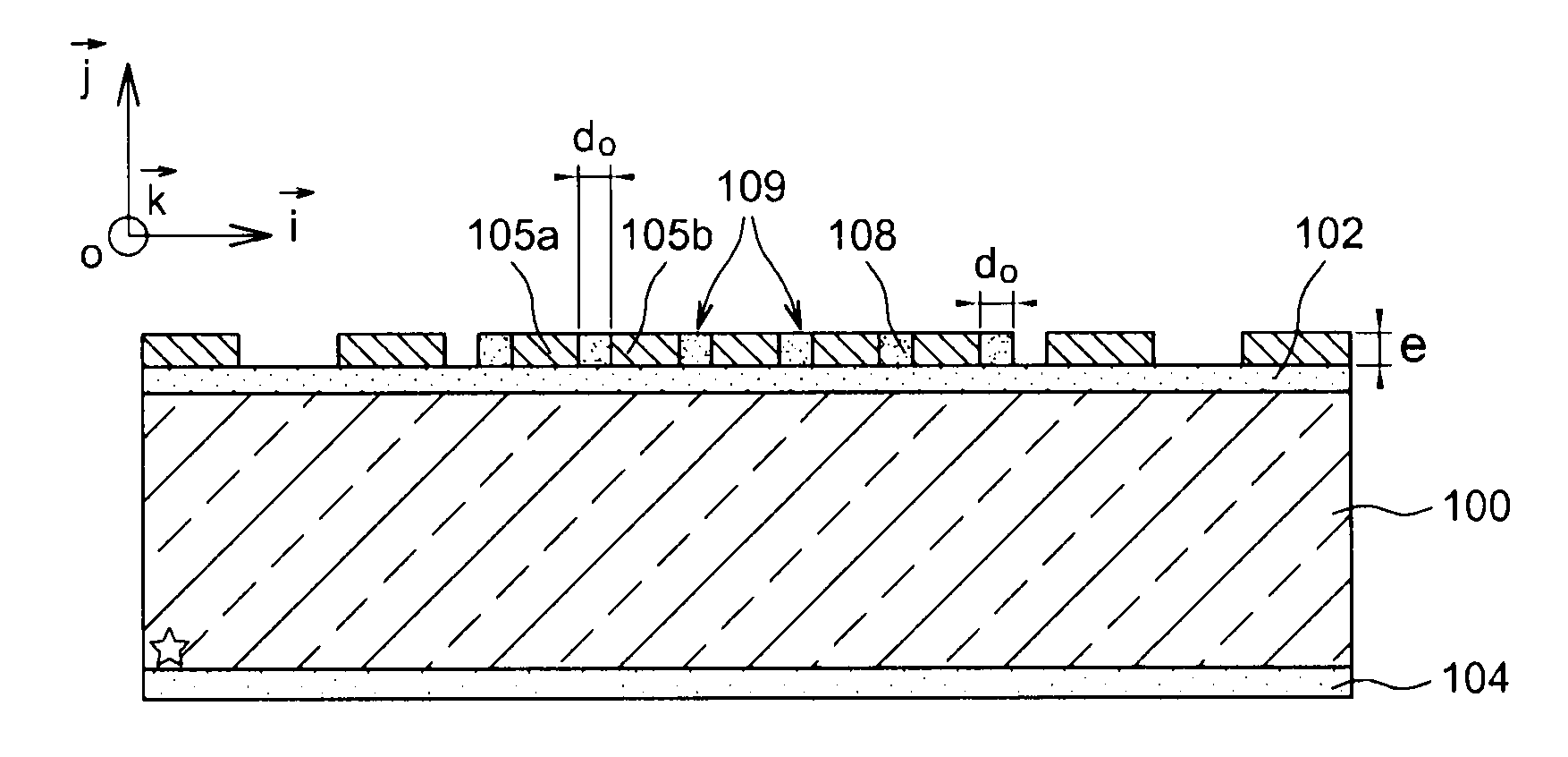
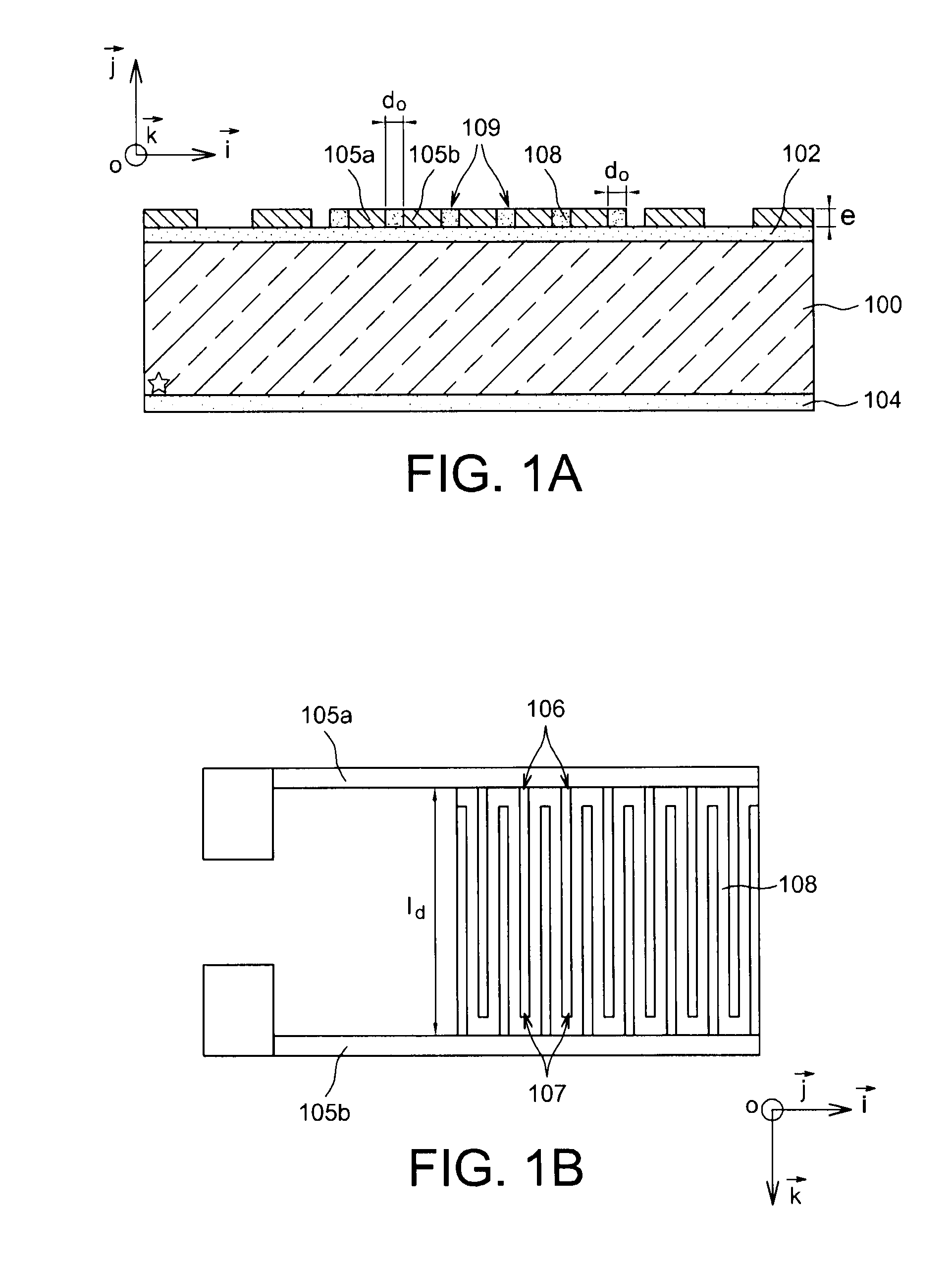
[0073]One example of a humidity sensor of capacitive type produced according to the invention is given in FIGS. 1A-1B.

[0074]The humidity sensor is formed on a substrate or wafer 100, which may be in semiconductor material e.g. Si. The wafer 100 is coated with insulating layers 102, 104, respectively on its upper face and lower face. For example, these insulating layers 102, 104 may be formed by thermal oxidation of the substrate.

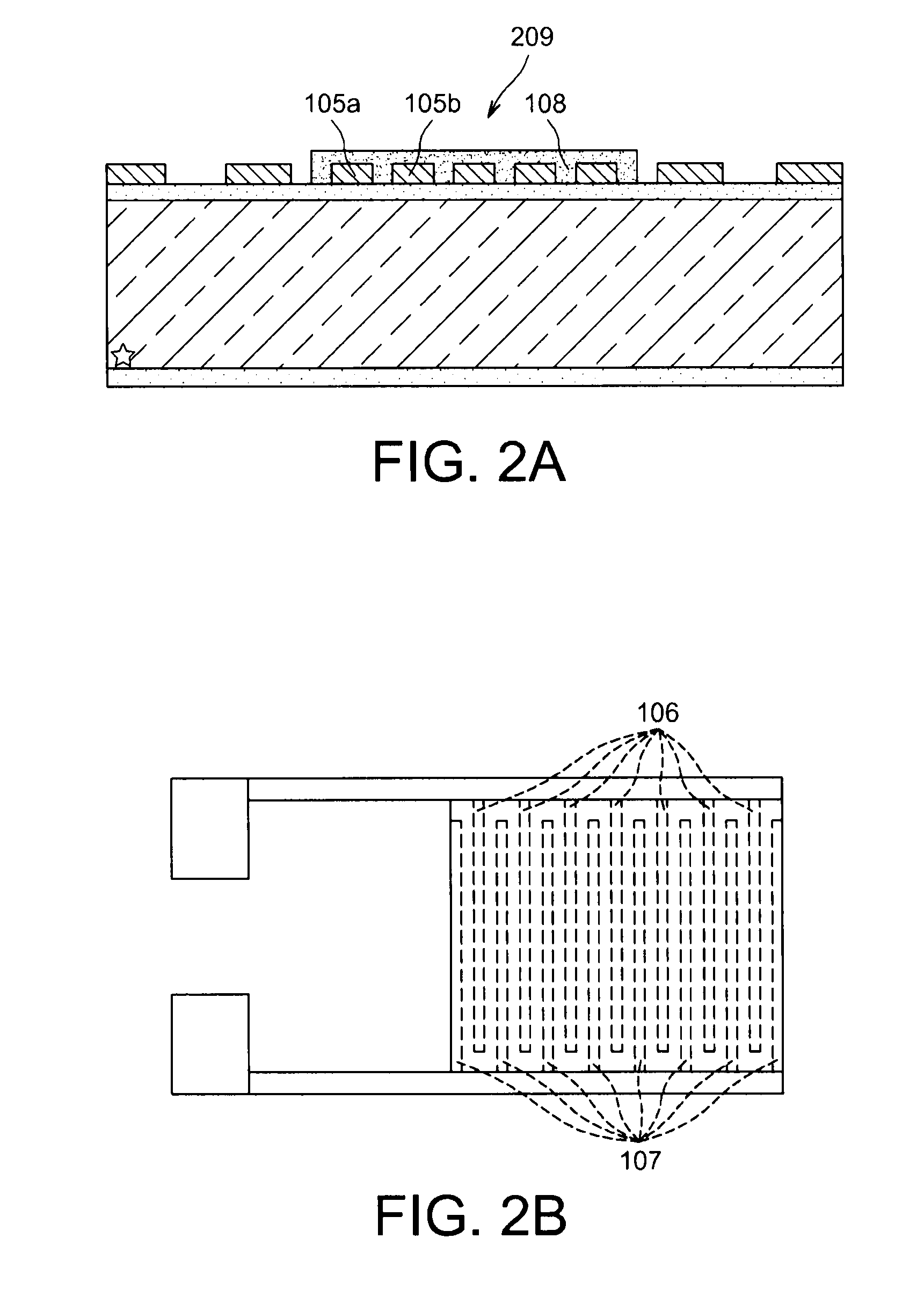
[0075]The sensor comprises electrodes 105a, 105b of at least one capacitor, which may each comprise a comb-shaped pattern. In FIG. 1B, the comb-shaped electrodes 105a, 105b have interdigitated teeth (respectively referenced 106 and 107).

[0076]The insulating layer 102 formed on the upper surface of the substrate can avoid the formation of short-circuits between the electrodes.

[0077]A nanoporous dielectric material 108 is positioned between electrodes 105a, 105b and in this example is distributed over the same plane as the latter. Therefore, the thickness e of...


PUM


Abstract

A humidity sensor of capacitive type, a device for detecting or measuring humidity including the sensor, and a method to fabricate the sensor. The humidity sensor includes at least one nanoporous dielectric material positioned between at least one first electrode of a capacitor and at least one second electrode of the capacitor.

Description

TECHNICAL FIELD[0001]The invention relates to the field of humidity detecting and / or measuring devices, in particular to humidity sensors of capacitive type.[0002]It concerns an improved humidity sensor device with nanoporous dielectric material allowing the detection of low humidity levels, and a method to fabricate said sensor.[0003]It also provides for a differential device to measure humidity using said sensor.[0004]The invention notably applies to the detection of humidity in encapsulated components such as integrated circuits, MEMS or NEMS.STATE OF THE PRIOR ART[0005]There are a large number of existing techniques and components to carry out measurement of humidity levels.[0006]The components used are generally adapted for measuring relative humidity from 0% to 100% RH.[0007]Throughout this description, the term relative humidity RH shall be used to designate the ratio between the quantity of water vapour contained in a given medium and the maximum quantity which could be cont...

Claims


Application Information

Patent Timeline
IPC IPC(8): G01N27/22H01L21/36B82Y15/00B82Y40/00
CPCB82Y15/00G01N27/225H01G5/16H01G5/0136H01G5/0134
Inventor GRANGE, HUBERTDANEL, JEAN-SEBASTIENDESLOGES, BRIGITTEJOUSSEAUME, VINCENT
Owner COMMISSARIAT A LENERGIE ATOMIQUE ET AUX ENERGIES ALTERNATIVES
Why Eureka
Try Eureka