Cold shrinkable secondary splice

Inactive Publication Date: 2011-07-28
RICHARDS MANUFACTURING COMPANY INC
View PDF6 Cites 15 Cited by
  • Summary
  • Abstract
  • Description
  • Claims
  • Application Information

AI Technical Summary

Problems solved by technology

Drawbacks to employing electrical tape and its splicing method include the large amount of time necessary to construct the splice and the necessary high skill level of the splicer to construct an adequate splice.
Drawbacks to employing this method include a large installation force necessary to store and position the housing.
It is also difficult to seal the splice if there are any protrusions such as phase markers or dips in the cable insulation surface from damage.
Drawbacks to this method include the use of a potentially dangerous torch.
Unfortunately, maintaining the position of the putty during core removal is problematic.
Another drawback to employing cold shrinkabl

Method used


Image

  • Cold shrinkable secondary splice
  • Cold shrinkable secondary splice
  • Cold shrinkable secondary splice

Examples


Embodiment Construction

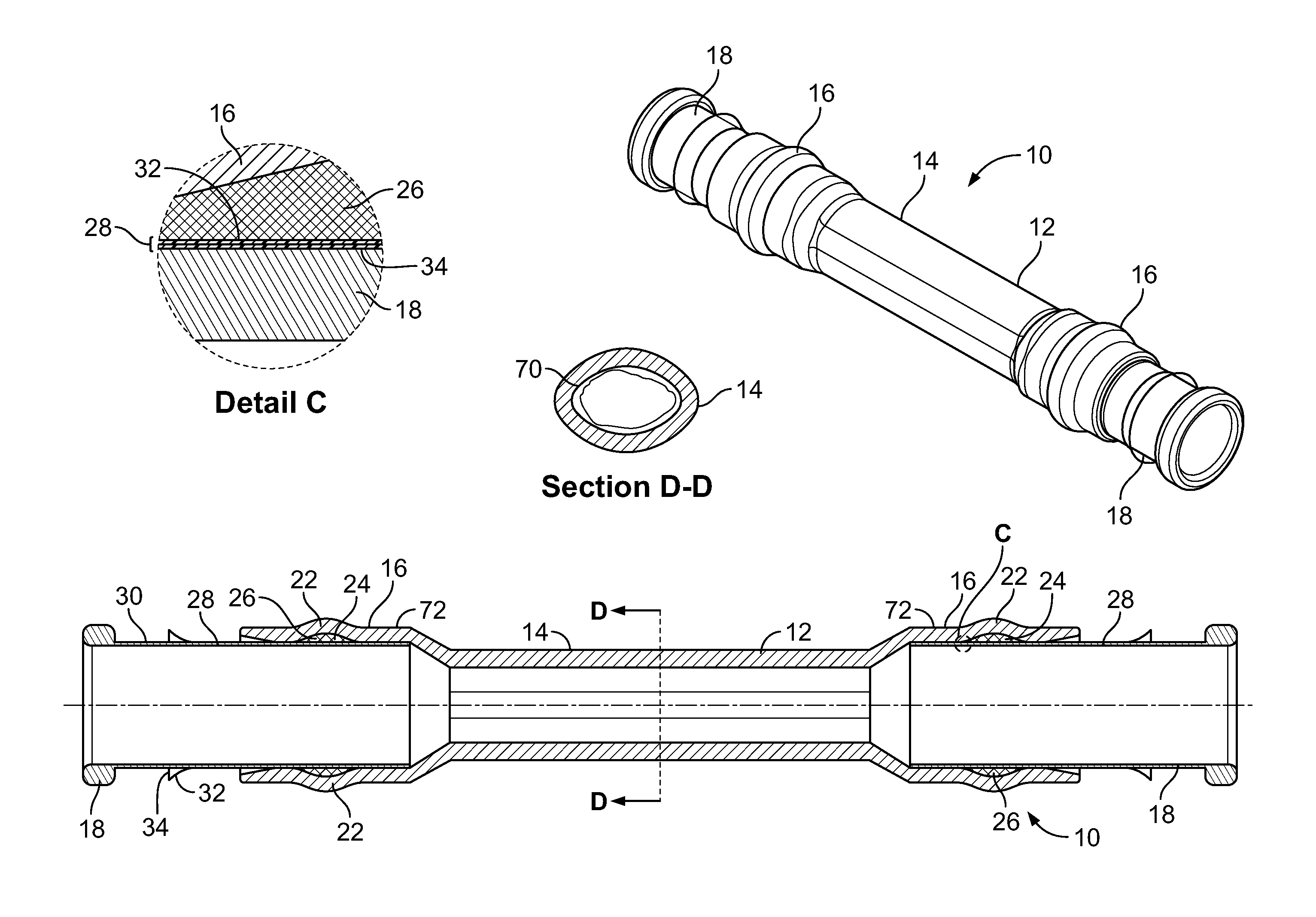
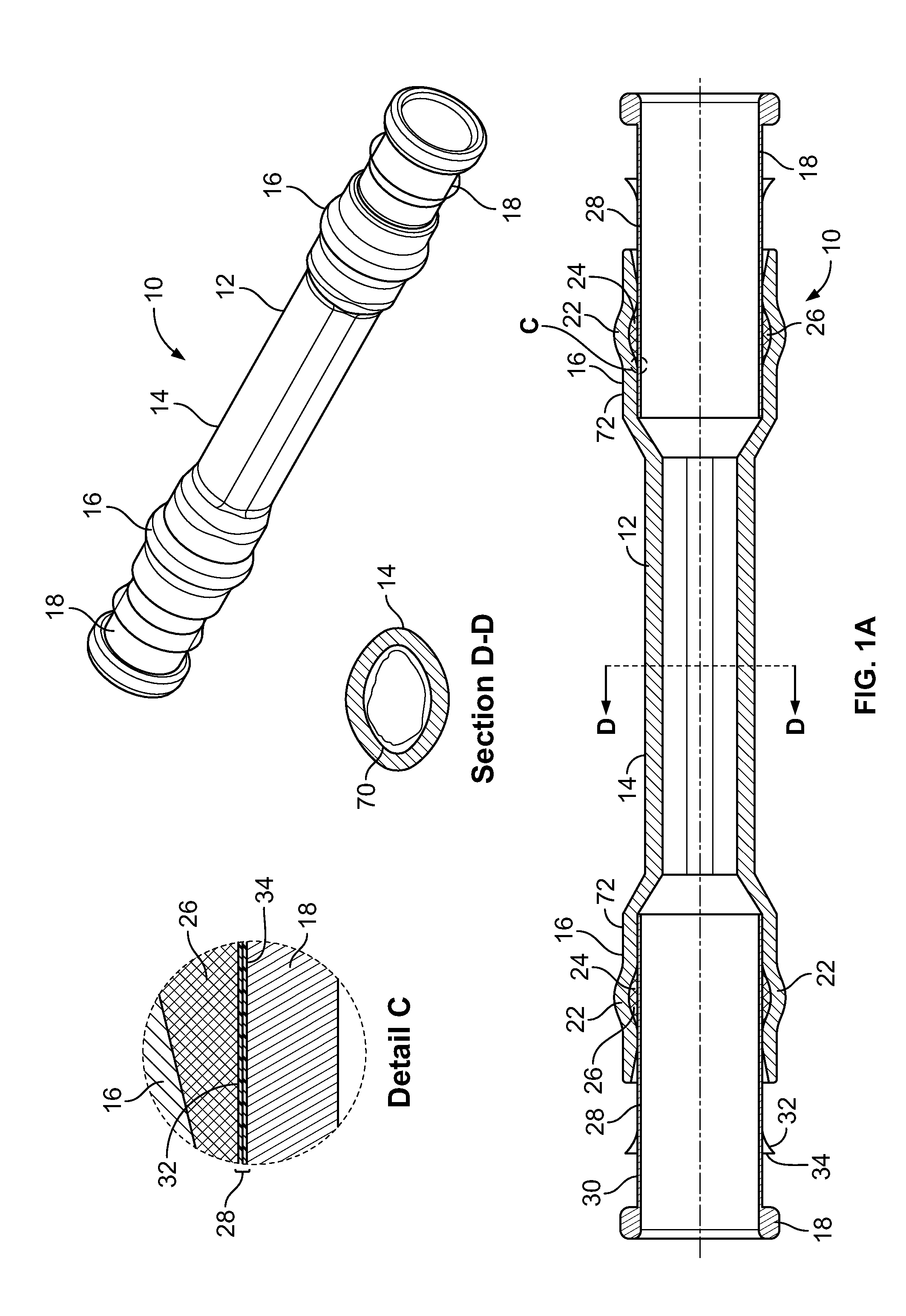
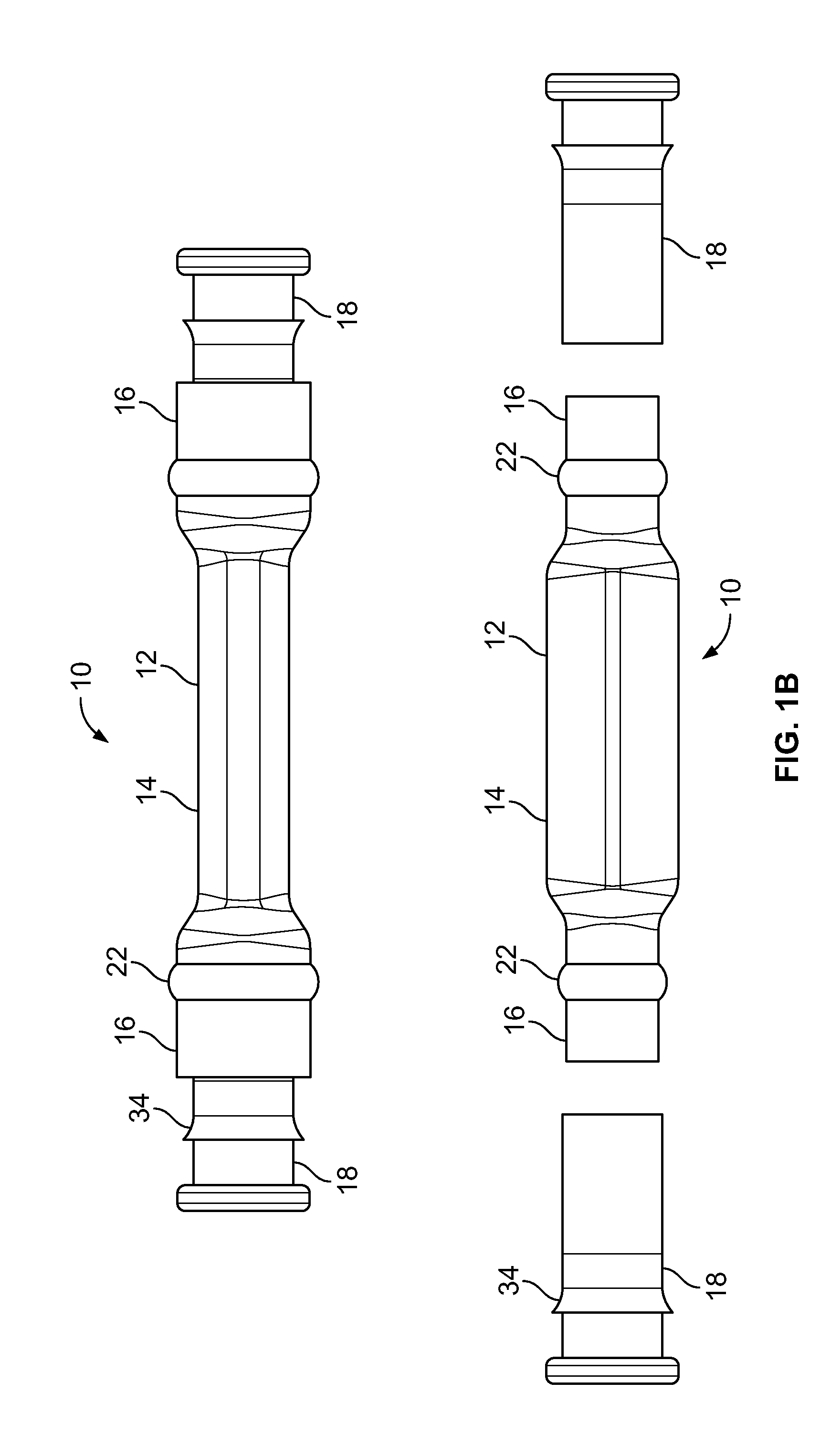
[0030]FIG. 1A depicts a plurality of assembled views of a cold-shrinkable splice insulating system 10 having solid support cores 18; FIG. 1B shows an exploded view of the insulating system 10 of FIG. 1A; FIG. 2A depicts a plurality of assembled views of a cold-shrinkable splice insulating system 10 having substantially spiral-shaped support cores 18′; and FIG. 2B shows an exploded view of the insulating system 10 of FIG. 2A, according to an embodiment of the present invention. Referring now to FIGS. 1A-2B, the insulating system 10 comprises a hollow insulating tube 12. The insulating tube 12 includes a central section 14 having a substantially elliptical cross-section and a pair of end sections 16 having a substantially circular cross-section. Each of the end sections 16 is constructed from a shape memory material. In a preferred embodiment, the shape memory material may comprise a form of rubber, such as Ethylene-propylene-diene-monomer (EPDM) or silicone.

[0031]The insulating syste...


PUM

PropertyMeasurementUnit
Lengthaaaaaaaaaa
Shape memory effectaaaaaaaaaa
Shapeaaaaaaaaaa

Abstract

An insulating system for splicing a pair of cables having at least partially exposed non-insulating portions joined with a metallic connector is disclosed. The insulating system includes an insulating tube constructed from a shape memory material having a central section having a substantially elliptical cross-section and a pair of end sections with substantially circular cross-sections. A pair of support cores is removably insertable in each of the end sections for holding the end sections in a stretched configuration. When the insulating system is placed about the cables and the connector and the support cores are removed from the end sections, the end sections return to a pre-stretched configuration, thereby completing a splice of the cables.

Description

CROSS-REFERENCE TO RELATED APPLICATIONS[0001]This application claims the benefit of U.S. Provisional Patent Application No. 61 / 297,337 filed Jan. 22, 2010, the disclosure of which is incorporated herein by reference in its entirety.FIELD OF THE INVENTION[0002]The present invention relates generally to cabling systems and connections, and more particularly, to a system and method for employing cold shrinkable materials for performing splicing on secondary cables.BACKGROUND OF THE INVENTION[0003]There is a need in several industries for splicing together two or more insulated cables containing solid or stranded wire. One such industry is the power transmission industry, which employs a myriad array of types of cables for different distribution needs. One such cable type used for low voltage distribution lines is secondary cable. As used herein “secondary cable” is intended to include cables configured to operate at about 600 volts or less and to be deployed on a low voltage side of a ...

Claims


Application Information

Patent Timeline
IPC IPC(8): H02G15/08H01R43/00
CPCH01R4/01H01R4/72Y10T29/49174H02G15/1833H01R43/005
Inventor LUZZI, GLENN J.
Owner RICHARDS MANUFACTURING COMPANY INC
Why Eureka
Try Eureka