Pedal driven apparatus having a motor

a technology of pedal drive and motor, which is applied in the direction of gearing, hoisting equipment, transportation and packaging, etc., can solve the problems of inability to develop an electric motor assisted bicycle on the wheel, inability to afford easy expansion of its functions, and inability to meet the needs of bicycle users

Active Publication Date: 2011-07-28
FOSTER ASSETS CORPORATION
View PDF6 Cites 43 Cited by
  • Summary
  • Abstract
  • Description
  • Claims
  • Application Information

AI Technical Summary

Benefits of technology

[0059]Preferably, a one way drive means is provided between the motor shaft and the sprocket such that when the sprocket is being driven by a manually provided driving force through pedals of the pedal driven apparatus, the motor shaft is not caused to rotate.
[0060]In a third main aspect of the invention, there is provided a sprocket assembly for a pedal driven apparatus, comprising: a sprocket; first means for mechanically coupling the sprocket to a pedal driven pedal spindle; and seco

Problems solved by technology

One consequence of the known in-wheel motor arrangement is that it is not feasible for an in-wheel electric motor assisted bicycle to be developed with additional functions such as gear shifting, operating with a clutch, functioning as an exercise bicycle, or using the motor to generate power, i.e. it does not afford easy expansion of its functions.
It also creates production and assembly problems as well as replacement parts problems.
Where an in-wheel motor fails or requires maintenance, for example, it requires the wheel to be removed thus disabling the bicycle.
Under

Method used


Image

  • Pedal driven apparatus having a motor
  • Pedal driven apparatus having a motor
  • Pedal driven apparatus having a motor

Examples


first embodiment

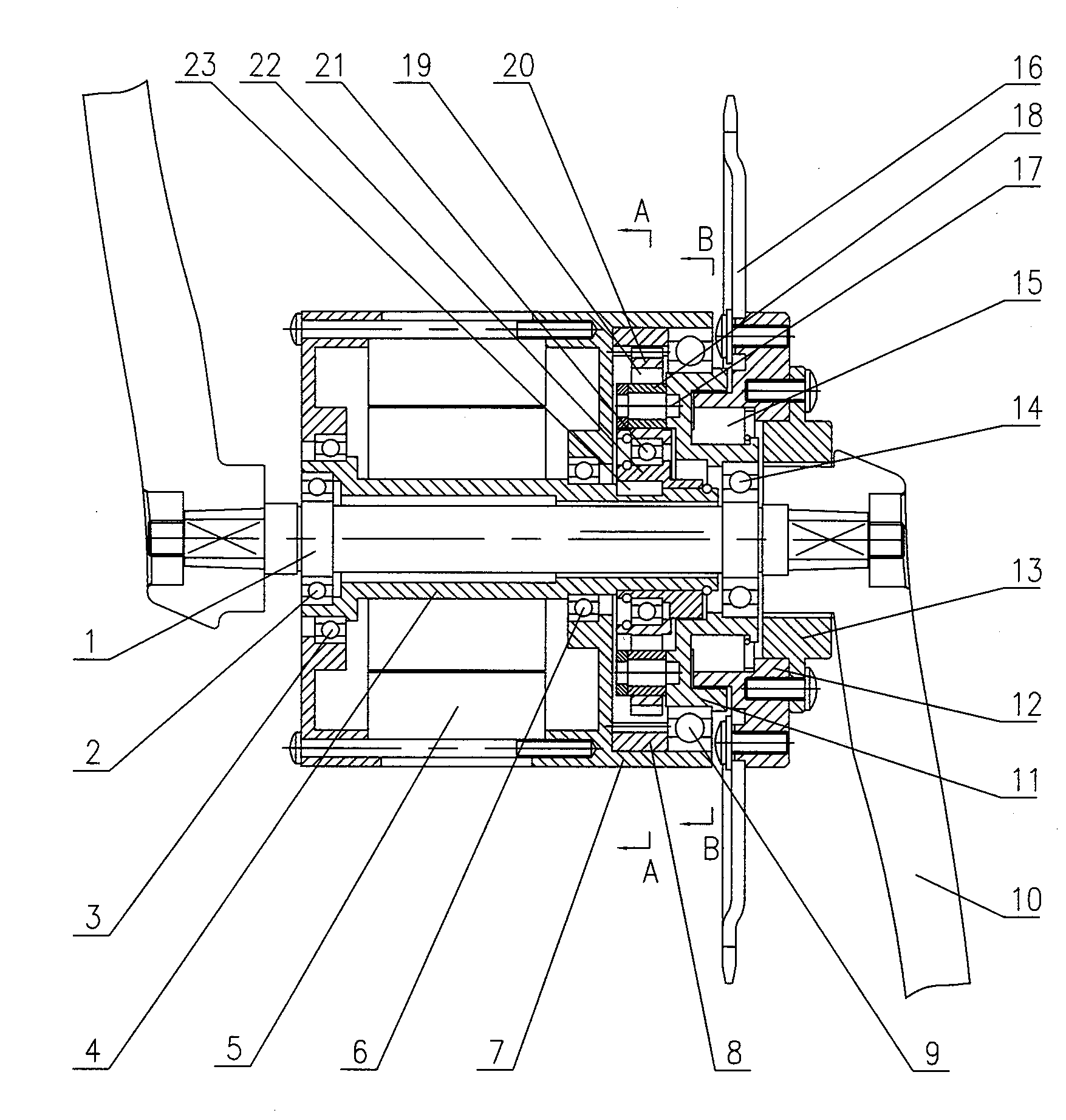
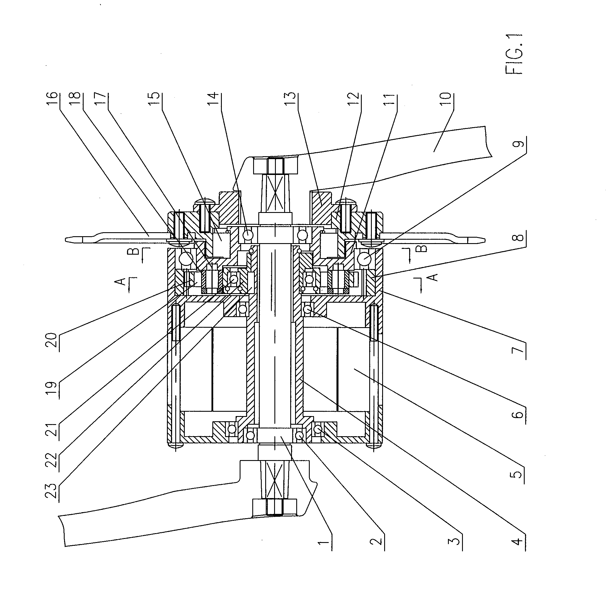
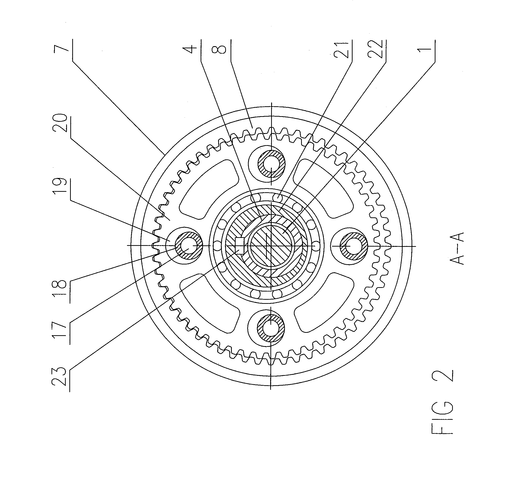
[0083]Referring to FIGS. 1 to 4, shown is a motor and sprocket assembly according to the invention. A bicycle having said motor and sprocket assembly comprises manually operable pedals 10 fixed for rotation with a pedal spindle 1 for receiving a manually provided driving force and a motor 5 having a shaft 4 for receiving a motor provided driving force. A first torque transmission path is provided for transferring the manually provided driving force to a sprocket 16 of the pedal driven apparatus and a second torque transmission path is provided for transferring the motor provided driving force to said sprocket 16 of the pedal driven apparatus. A first one way drive means 13 is provided in the first torque transmission path between the pedal spindle 1 and the sprocket 16 such that, when the sprocket is being driven by the motor provided driving force through the second torque transmission path, the pedal spindle 1 is able to freewheel.

[0084]An advantage of this arrangement is that it ...

second embodiment

[0100]FIG. 5 depicts the motor and sprocket assembly according to the invention. In the description of this embodiment, like numerals to those used in FIGS. 1 to 4 are used to denote like parts, although any differences in the parts are described in the following.

[0101]In this embodiment, the second one-way drive or transmitting means, (i.e. the ratchet wheel 12 and ratchets 15), is omitted, so that the planet gear carrier 11′ of the planetary gear mechanism is fixedly coupled to the sprocket 16 for rotation therewith. The planet gear 20 and the sprocket 16 are directly and fixedly connected with the (output member of) one-way freewheel 13 of the first one-way drive / transmitting means. As such, the planet gear carrier 11′ is modified compared to its configuration in the first embodiment of FIGS. 1 to 4 to enable it to be directly and fixedly connected with the one-way freewheel 13. In this embodiment, the direct coupling of the planet gear carrier 11′ to the freewheel 13 enables the...

third embodiment

[0104]FIG. 6 depicts the motor and sprocket assembly according to the invention. In the description of this embodiment, like numerals to those used in FIGS. 1 to 5 are used to denote like parts, although any differences in the parts are described in the following.

[0105]In this embodiment, the planetary gear mechanism does not include a weighted counterbalance member, but comprises first and second identical planet gears 20, 26 arranged half a revolution out of phase with each other such that said first and second planet gears 20, 26 counterbalance each other on rotation. The first and second planet gears 20, 26 may be located within respective internal ring gears, but are preferably located for rotation half a revolution out of phase with each other within a common, single internal ring gear 8′ of double width compared to the internal ring gear of the first or second embodiments. The first and second planet gears 20, 26 are supportably mounted on respective first and second eccentri...


PUM


Abstract

A hybrid bicycle is provided which can be manually propelled, but which includes a motor unit for also causing forward propulsion of the bicycle. The bicycle comprises manually operable pedals fixed for rotation with a pedal spindle for receiving a manually provided driving force and a motor having a shaft for receiving a motor provided driving force. A first torque transmission path is provided for transferring the manually provided driving force to a sprocket of the pedal driven apparatus and a second torque transmission path is provided for transferring the motor provided driving force to said sprocket of the pedal driven apparatus. A first one way drive means is also provided. This is provided in the first torque transmission path between the pedal spindle and the sprocket such that when the sprocket is being driven by the motor provided driving force through the second torque transmission path, the pedal spindle is able to freewheel. The second torque transmission path may include a gear mechanism mechanically coupling the motor shaft to the sprocket of the pedal driven apparatus. The gear mechanism has a reduction gear ratio and operates to transfer the motor provided driving force from the motor shaft to the sprocket at said reduction gear ratio. The motor may be arranged concentrically around a pedal spindle of the pedal driven apparatus such that the pedal spindle is freely accommodated through a hollow bore of the motor shaft and such that their axes of rotation are parallel and preferably co-incident.

Description

FIELD OF THE INVENTION[0001]The invention relates to a pedal driven apparatus which can be manually propelled, but which includes a motor unit for also causing forward propulsion of the apparatus. The invention relates particularly, but not exclusively, to pedal driven wheeled apparatuses or vehicles such as bicycles having an electric motor powered by a battery pack carried on the vehicle.BACKGROUND OF THE INVENTION[0002]It is known to provide some manually propellable wheeled vehicles or apparatuses such as bicycles with a motor unit to assist a user in powering the apparatus, especially up sloping terrain, e.g. hills, although the motor unit may sometimes used by itself to power the bicycle over any terrain.[0003]It is also known to utilize an in-wheel motor in an electric motor assisted bicycle such that a transmission can be omitted and the resulting apparatus is easy and simple to manufacture. For such a known electric motor assisted bicycle using an in-wheel motor, it can be ...

Claims


Application Information

Patent Timeline
IPC IPC(8): B62M23/02F16H3/72F16H55/30
CPCB62M6/55F16H2001/325Y10T74/19051F16H55/30F16H3/724
Inventor CHAN, YET
Owner FOSTER ASSETS CORPORATION
Why Eureka
Try Eureka