Method and apparatus for improving power generation in a thermal power plant

a technology for thermal power plants and power generation, applied in the direction of electric generator control, process and machine control, instruments, etc., can solve the problems of reducing overall transmission efficiency, reducing power factor circuits, reducing power generation efficiency, etc., and achieve the effect of improving power generation

Inactive Publication Date: 2011-07-28
ABB POWER GRIDS SWITZERLAND AG
View PDF6 Cites 29 Cited by
  • Summary
  • Abstract
  • Description
  • Claims
  • Application Information

AI Technical Summary

Benefits of technology

[0008]In accordance with the present invention, a method is provided for improving power generation in a thermal power plant having a power generator connected to a high voltage bus. In accordance with the method, a dynamic reactive compensation system (DRCS) is provided that includes one or more power electronic devices. The DRCS is connected to the high voltage bus of the power plant and is operated to provide most of the reactive power required to be provided from the the

Problems solved by technology

These higher currents in a power system will produce higher losses and reduce overall transmission efficiency.
A lower power factor circuit will have a higher apparent power and higher losses for the same amount of real power transfer.
Without such voltage support, the trans

Method used


Image

  • Method and apparatus for improving power generation in a thermal power plant
  • Method and apparatus for improving power generation in a thermal power plant
  • Method and apparatus for improving power generation in a thermal power plant

Examples


Embodiment Construction

[0022]It should be noted that in the detailed description that follows, identical components have the same reference numerals, regardless of whether they are shown in different embodiments of the present invention. It should also be noted that in order to clearly and concisely disclose the present invention, the drawings may not necessarily be to scale and certain features of the invention may be shown in somewhat schematic form.

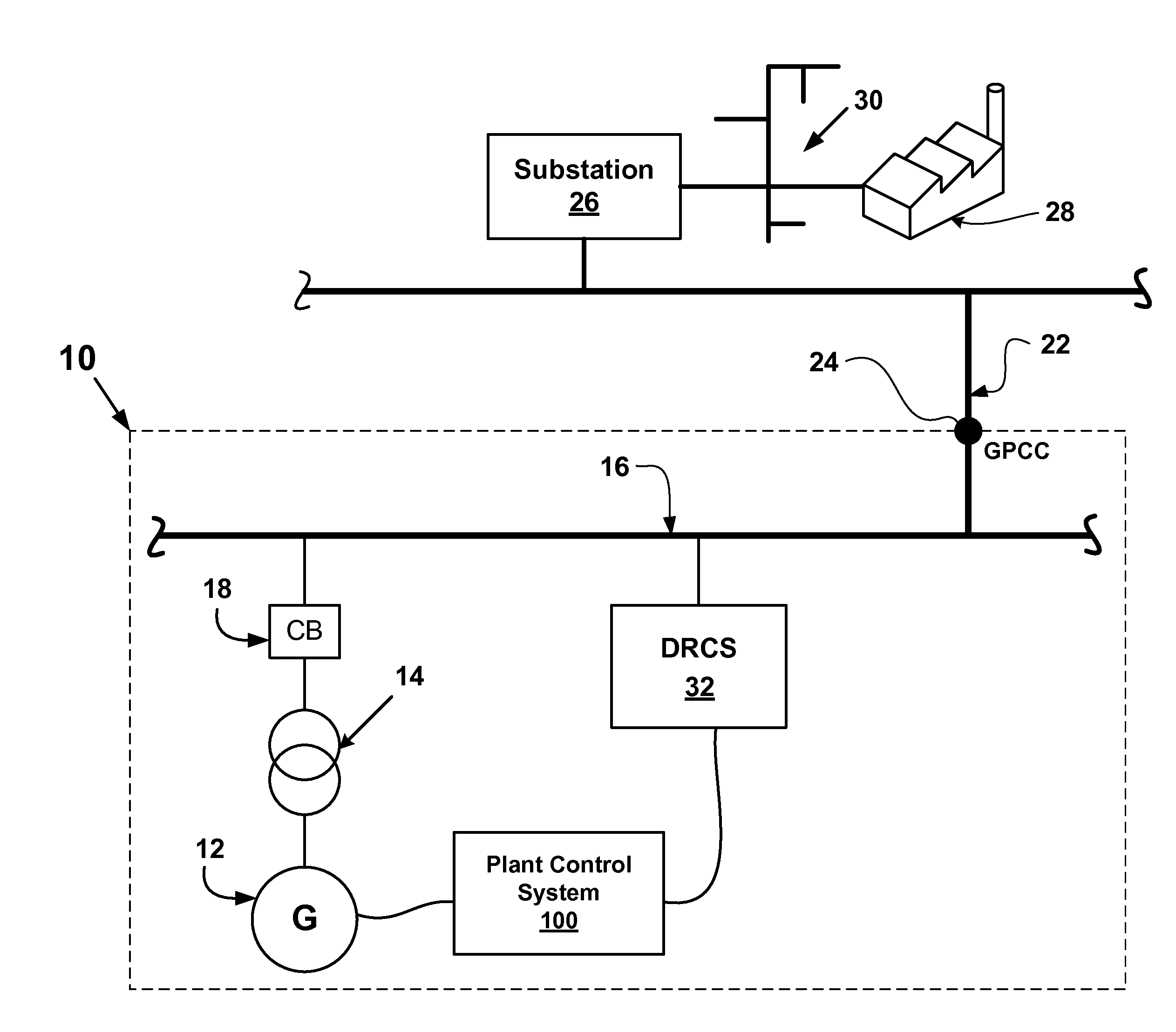
[0023]Referring now to FIG. 1 there is shown a schematic drawing of a power generation station 10 in which the method and apparatus of the present invention may be utilized. The generation station 10 may be a thermal power plant, such as a coal-fired power plant, a nuclear power plant, a solar power plant, or a geothermal power plant. The generation station 10 includes a generator 12 that generates electricity from mechanical energy supplied by one or more steam-driven turbines (not shown). The output of the generator 12 typically has a voltage in a range of...


PUM


Abstract

A method and apparatus for improving power generation in a thermal power plant. A dynamic reactive compensation system is provided and is connected to a high voltage bus or a generator bus of the power plant. The dynamic reactive compensation system comprises power electronic devices and is operable to provide most of the reactive power that is required from the power plant.

Description

CROSS-REFERENCE TO RELATED APPLICATION[0001]This application claims the benefit of U.S. provisional patent application No. 61 / 297,672 filed on Jan. 22, 2010, which is hereby incorporated by reference in its entirety.BACKGROUND OF THE INVENTION[0002]The present invention relates to thermal power plants and more particularly to methods and apparatus for improving power generation in thermal power plants.[0003]The portion of power flow that results in a net transfer of energy in one direction (over a complete AC waveform cycle) is known as real power (or useful or active power). That portion of power flow that is due to stored energy in the load returning to the source in each cycle is known as reactive power. Apparent power is the vector sum of real and reactive power.[0004]The power factor of an AC power system is defined as the ratio of real power to apparent power, and is a number between 0 and 1. Where the waveforms are purely sinusoidal, the power factor is the cosine of the phas...

Claims


Application Information

Patent Timeline
IPC IPC(8): G05F1/70
CPCY02E40/12H02J3/1864Y02E40/10
Inventor SCOTT, BRIAN DAVIDLARSSON, DAVID
Owner ABB POWER GRIDS SWITZERLAND AG
Why Eureka
Try Eureka