

Intelligent automatic peritoneal dialysis
a technology of intelligent peritoneal dialysis and automatic peritoneal dialysis, which is applied in the direction of peritoneal dialysis, other medical devices, suction devices, etc., can solve the problems of patient discomfort and the inability to smoothly drain waste liquid from the body, and achieve the effect of improving dialysis efficiency
- Summary
- Abstract
- Description
- Claims
- Application Information
AI Technical Summary
Benefits of technology
Problems solved by technology
Method used
Image

Examples
example 1
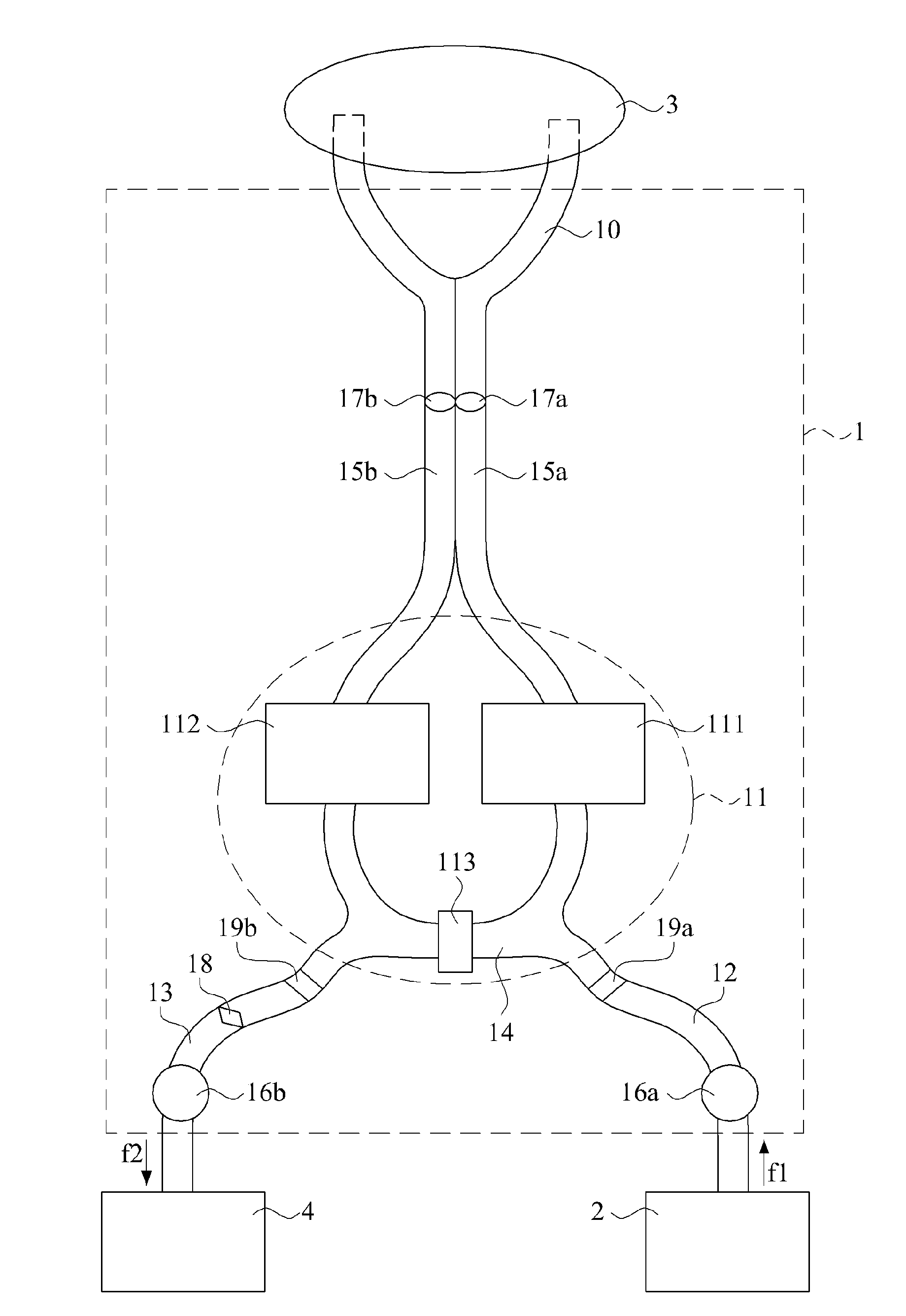
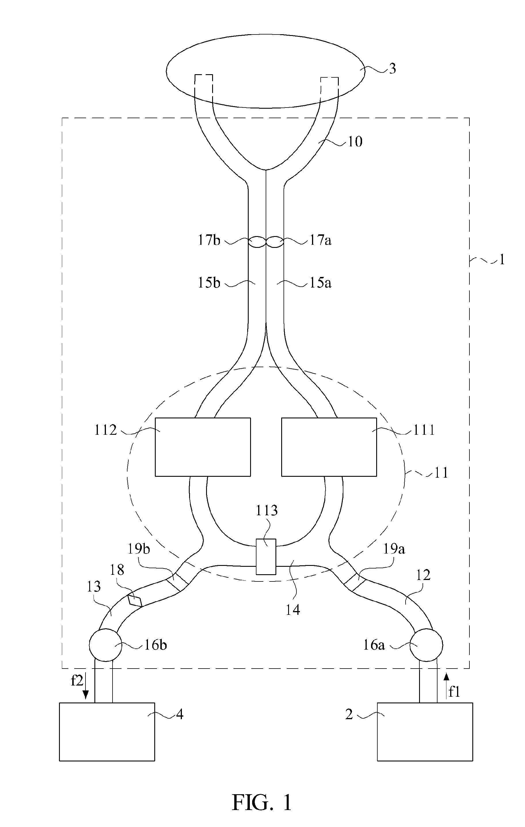
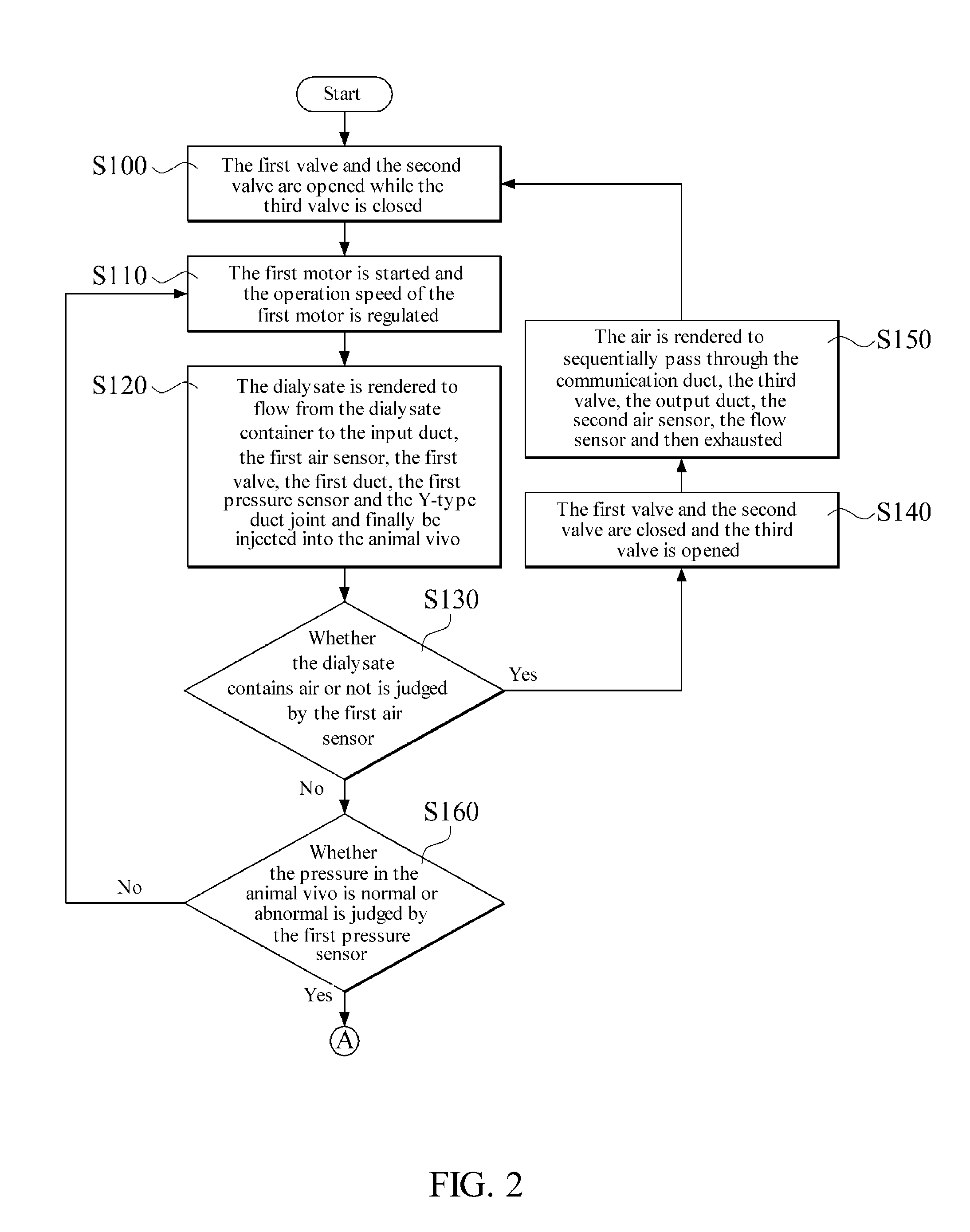
[0043]The first valve 111 and the second valve 112 are initially opened and the third valve 113 is closed when the operation method is performed. Next, the first motor 16a is started such that the dialysate f1 flows from the dialysate container 2 to the input duct 12, the first air sensor 19a, the first valve 111, the first duct 15a, the first pressure sensor 17a and the Y-type duct joint 10. The dialysate f1 is then injected into the live animal 3.
[0044]The dialysate f1 may remain in the animal 3 for a period of time. A diffusion exchange and an osmosis exchange take place in the animal 3 via a peritoneum of the animal 3 while the dialysate f1 remains in the animal 3. Therefore, waste products in the blood will pass through blood capillaries on the peritoneum and enter the dialysate f1. The waste liquid f2 will be formed after a period of time.
[0045]Next, the waste liquid f2 may flow from the animal 3 to the Y-type duct joint 10, the second duct 15b, the second pressure sensor 17b,...
example 2
[0053]Initially, the first valve 111 is closed and the second valve 112 and the third valve 113 are opened when the method is performed. Next, the first motor 16a is started such that the dialysate f1 flows from the dialysate container 2 to the input duct 12, the first air sensor 19a, the communication duct 14, the third valve 113, the second valve 112, the second duct 15b, the second pressure sensor 17b and the Y-type duct joint 10. Finally, the dialysate f1 is injected into the live animal 3.
[0054]The dialysate f1 may remain in the animal 3 for a period of time. The diffusion exchange and the osmosis exchange may be performed in the animal 3 via the peritoneum of the animal 3 during the dialysate f1 remaining in the animal 3. Therefore, the waste products in the blood will pass through the blood capillaries on the peritoneum and enters the dialysate f1. The waste liquid f2 will be formed after a period of time.
[0055]Next, the first valve 111 and the third valve 113 are opened and ...
example 3
[0058]Initially, the first valve 111 is opened and the second valve 112 and the third valve 113 are closed when the method is performed. Next, the first motor 16a is started such that the dialysate f1 flows from the dialysate container 2 to the input duct 12, the first air sensor 19a, the first valve 111, the first duct 15a, the first pressure sensor 17a and the Y-type duct joint 10. Finally, the dialysate f1 is injected into the live animal 3.
[0059]The dialysate f1 may remain in the animal 3 for a period of time. The diffusion exchange and the osmosis exchange take place in the animal 3 via the peritoneum of the animal 3 while the dialysate f1 remains in the animal 3. Therefore, the waste products in the blood will pass through the blood capillaries on the peritoneum and enter the dialysate f1. The waste liquid f2 will be formed after a period of time.
[0060]Next, the first valve 111, the second valve 112 and the third valve 113 are opened. Then the waste liquid f2 may flow from the...
PUM
 Abstract
Description
Claims
Application Information