
Probe for implantable electro-stimulation device

a technology of electrostimulation device and probe, which is applied in the direction of localised screening, artificial respiration, therapy, etc., can solve the problems of device and surrounding tissue heat, and achieve the effect of reducing one, alleviating one, and eliminating on

Active Publication Date: 2011-07-28
MEDTRONIC BAKKEN RES CENT
View PDF11 Cites 30 Cited by
  • Summary
  • Abstract
  • Description
  • Claims
  • Application Information

AI Technical Summary

Benefits of technology

[0008]Accordingly, the invention preferably seeks to mitigate, alleviate or eliminate one or more of the above mentioned disadvantages singly or in any combination. In particular, it may be seen as an object of the present invention to provide an implantable electro-stimulation device that reaches the above mentioned objectives with regard to battery life time, focused electro-stimulation and safety with regard to external fields.
[0010]The shield of conducting material is integrated onto the probe, the shield being partly covered by an insulating layer. The part of the shield not covered by the insulating layer, viz. the exposed part of the shield, provides a return electrode for a stimulating current path. The shield may cover most of the length of the probe and thus protect an enclosed wire extending from the one or more electrodes at the distal end of the probe to the proximal end of the probe against external electromagnetic fields, such as external RF fields. Thus, the shield with a layer of insulating material on a part thereof adjacent to at least one of the one or more electrodes, solves boths problems regarding RF safety and a return path of stimulation current.
[0015]According to an aspect of probe, the exposed area of the shield not covered by the layer of insulating material is at least one order of magnitude larger than the area of an individual electrode amongst the one or more electrodes. Hereby, the return electrode created by the exposed area of the shield is large compared to the one or more electrodes individually; this ensures that the current density at the return electrode does not elicit unwanted stimulation effects.
[0017]According to another aspect of the probe, the impedance of the insulating material is sufficiently low at high frequencies to become substantially transparent. The term “high frequencies” is a well-defined term denoting frequencies above 30 MHz. Typical MR frequencies are in the range from 64 to 128 MHz, viz. very high frequencies. Thus, the insulating material is substantially transparent to MR frequencies, which means that the current distribution at these MR frequencies is not changed by the insulating material. Thus, the insulating material does not influence the current distribution at MR frequencies, and the insulating material does not inhibit the shielding effect of the shield of conductive material. Therefore, the shielding effect of the shield of conductive material is effective along the entire extension of the shield of conductive material, not just at the exposed part thereof.

Problems solved by technology

After implant of an implantable device for electric stimulation, such as pacemakers or Deep Brain Stimulation (DBS) devices, the device may cause heating of the device and surrounding tissue, either at the normal use of the implantable device or during scanning of the patient and device by e.g. Magnetic Resonance (MR) scanning.

Method used


Image

  • Probe for implantable electro-stimulation device
  • Probe for implantable electro-stimulation device
  • Probe for implantable electro-stimulation device

Examples


example

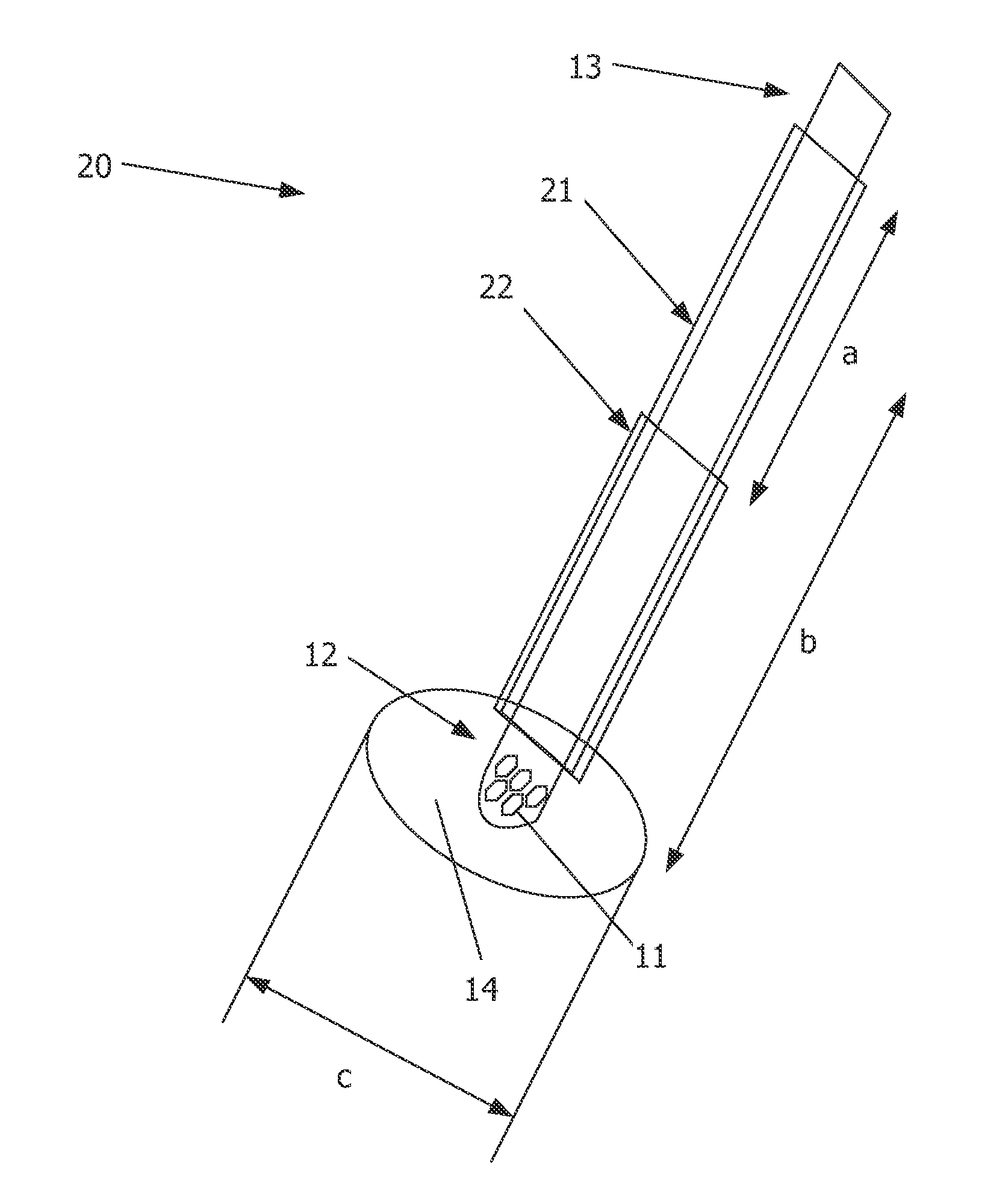
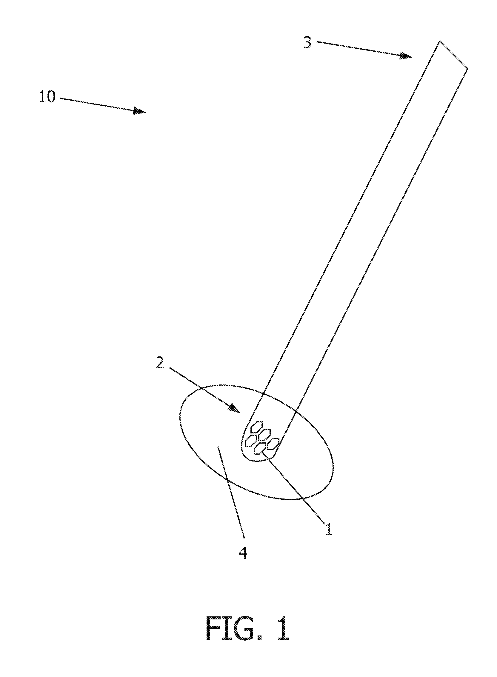
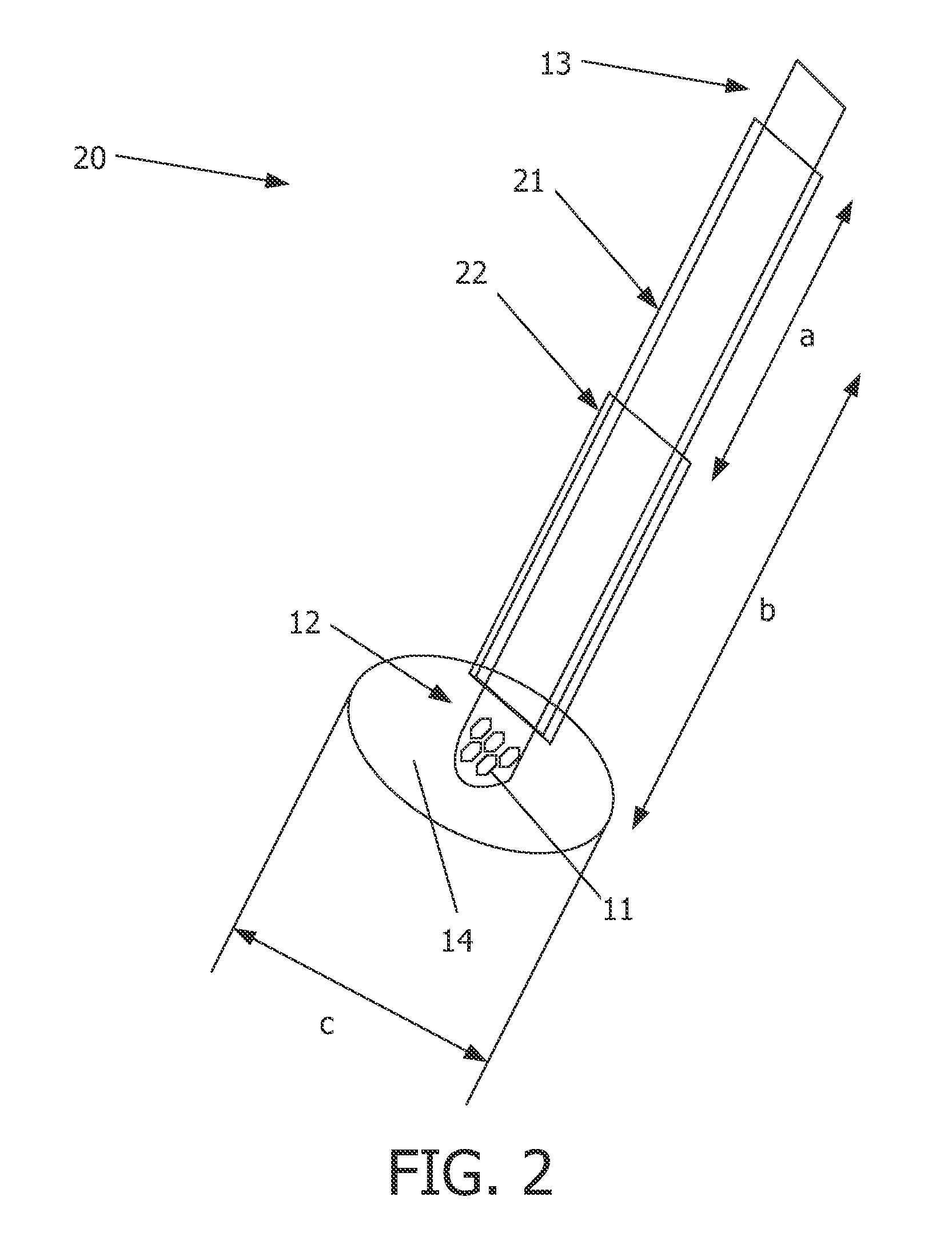
[0054]Numeral values of the impedance of a probe are given in the following, only as an example. These values are thus not to be taken as limiting the invention.

[0055]In general, the capacitive impedance of the insulating layer needs to be high enough at neuro-stimulation frequencies, typically 0.001-10 kHz, to effectively block the current flow. On the other hand, the impedance of the insulating layer should be low enough at MR frequencies, typically 64-128 MHz, so that the insulating layer becomes relatively transparent. Thus the induced current can spread across the entire shield instead of accumulating at some parts.

[0056]The capacitance of two concentric cylindrical shells of length L and respective radii r1 and r2 is given by

C=2πɛ0ɛrLln(r2 / r1)

Therefore, the impedance of a cylindrical layer with diameter d and thickness t for a signal with frequency f is given by

Z=12πfC=ln(1+2t / d)4π2ɛ0ɛrL

Calculations of this impedance using typical values in a DBS probe are presented in Table 1...


PUM


Abstract

The invention relates to a probe for an implantable electro-stimulation device. The probe (20) has a distal end (12) and a proximal end (13), and moreover comprises: one or more electrodes (11) a shield (21) of conducting material covering a major part of the probe, said shield extending from the vicinity of at least one of the one or more electrodes (11) towards the proximal end (13) or towards the distal end (12) of the probe (20); and a layer (22a, 22b) of insulating material covering part of the shield (21) in the vicinity of the at least one of the one or more electrodes. The shield protects wires (14), extending from electrodes to the proximal end of the probe, from undesired interference of external RF fields. The exposed part of the shield not covered by the layer of insulating material serves as a return electrode for the electrostimulation signal path.

Description

FIELD OF THE INVENTION[0001]The present invention relates to a probe for an implantable electro-stimulation device.BACKGROUND OF THE INVENTION[0002]Implantable electro-stimulation devices are commonly used today to treat patients suffering from various ailments. After implant of an implantable device for electric stimulation, such as pacemakers or Deep Brain Stimulation (DBS) devices, the device may cause heating of the device and surrounding tissue, either at the normal use of the implantable device or during scanning of the patient and device by e.g. Magnetic Resonance (MR) scanning.[0003]The human tissue, in particular brain tissue, is sensitive to temparature raises; the maximum allowed temperature increase of brain tissue is 1° C. in that further temperature increases may have profound, negative effects on single neuron and neuronal network function. Therefore it is of concern to minimize heating effects at and around an implanted electro-stimulation device as well as to preven...

Claims


Application Information

Patent Timeline
Patent Type & Authority Applications(United States)
IPC IPC(8): A61N1/36
CPCA61N1/05A61N1/0529A61N1/0531H05K9/002A61N1/056A61N2001/086A61N1/0551A61N1/086
Inventor WANG, KEMARTENS, HUBERT CECILE FRANCOISBUDZELAAR, FRANCISCUS PAULUS MARIAHARBERTS, DIRK WILLEMDECRE, MICHAEL MARCEL JOSETOL, JEROEN JACOB ARNOLD
Owner MEDTRONIC BAKKEN RES CENT
Learn More