In many cases, these aircraft are inherently unstable to begin with, and adding the stability
control system acts primarily to make the aircraft behave more like a traditional helicopter.
Thus it becomes not much easier to
pilot than a conventional helicopter.
Stability control systems do not make these aircraft “easy” to fly for the inexperienced
pilot.
When the
pilot is situated remotely, this difficultly is compounded as the pilot not only has less sensory information from which to work, but is also outside the aircraft which takes on various different orientations relative to the pilot.
It is thus commonly known that learning just the basics of hovering a VTOL aircraft can take a great deal of time.
This is problematic because
forward flight typically requires that changes in attitude be employed.
Furthermore, if these limitations are exceeded, due to wind or another cause, the
system may become unstable.
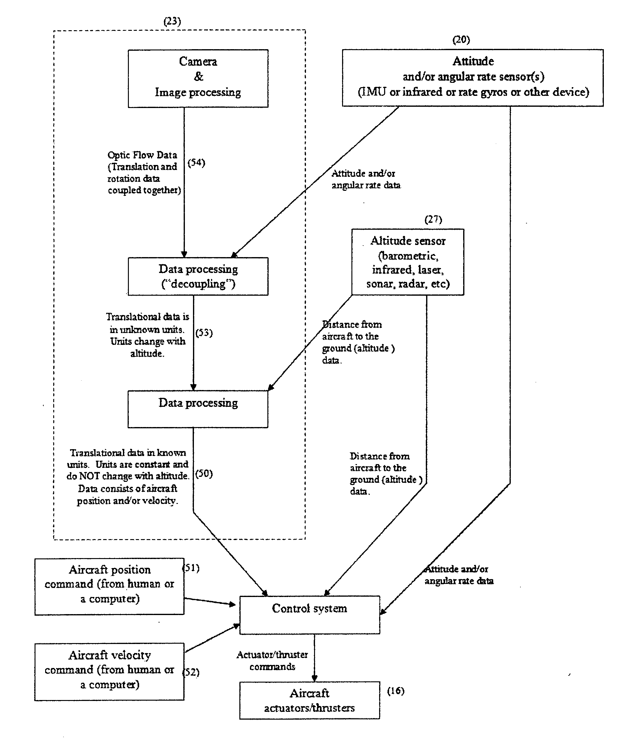
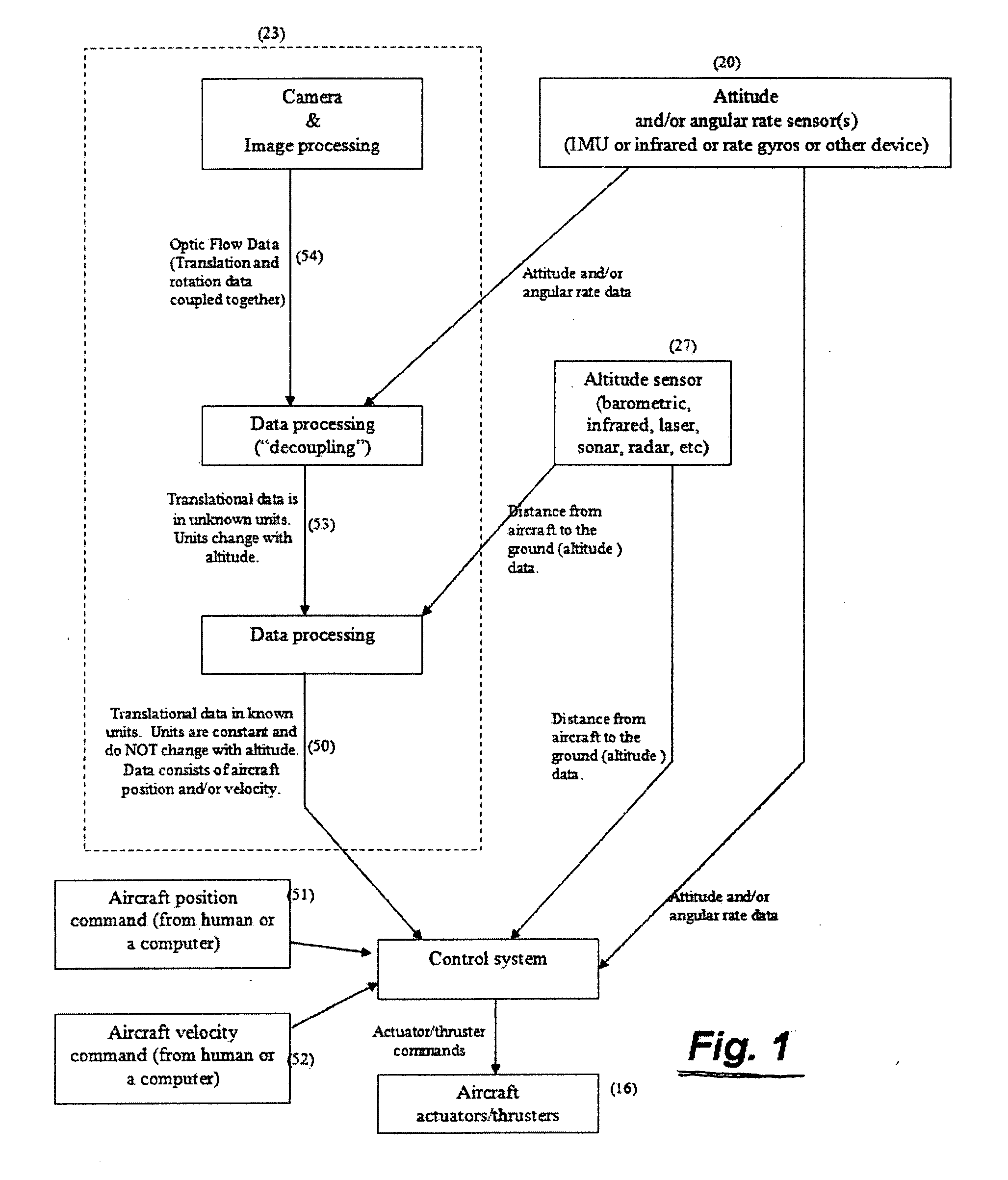
In addition, it is clear that the
system does not provide substantial stability over its
visual range as the aircraft approaches or departs from the ground, since the vision system does not compensate for altitude.
This is problematic because at low elevations, such as during landing, increased stability is critical.
Additionally, the “position hold” capabilities of the system are not true position hold.
Thus, the system is inherently susceptible to translational drift.
Thus, any move of the aircraft due to inaccuracies in calibration,
noise in the sensors, or wind, will not be reversed by the system, and drift of the aircraft will occur.
First, GPS can suffer from lack of reception if weather, buildings, or geography separates the aircraft from some of the satellites on which GPS depends. During these conditions, GPS can be useless. Furthermore, lack of reception is most likely to happen at low altitudes during take-offs and landings, when precision is most needed. Hence, by its nature the use of GPS depends on complex external
technical systems in order to function. The
dependability of these external technological systems is questionable in a wartime environment and when the aircraft is operating in canyons, near buildings, and other areas where GPS reception is weak.
Another drawback to GPS based systems is that traditional GPS does not have the
high resolution or update rate needed to provide enough localization to allow real-
time control during take-offs and landings.
These systems are expensive, and require the ground based
beacon to be installed and running near the point of flight for the aircraft.
The use of these beacons also adds an additional external technological dependency to the system, further reducing the reliability of the system.
This ultimately makes both standard GPS and
differential GPS inadequate to provide useful position and velocity information for many near-Earth applications.
Because of the aforementioned difficulties and other limitations, unmanned VTOL aircraft have typically been unpractical for many applications.
In addition to the above difficulties and problems, many of the previous systems would be too large and heavy for application on micro UAVs, which may weigh under a pound.

