Gas sensor and method for manufacturing same

a technology of gas sensor and manufacturing method, which is applied in the field of gas sensor, can solve the problems of increasing the impedance between the inner and outer pump electrodes, reducing the measurement accuracy, and the technique of simply covering the outer pump electrodes with porous protective layers, and achieves the effects of preventing light-off time, high measurement accuracy, and small thermal capacity

Active Publication Date: 2011-08-04
NGK INSULATORS LTD
View PDF5 Cites 63 Cited by
  • Summary
  • Abstract
  • Description
  • Claims
  • Application Information

AI Technical Summary

Benefits of technology

[0013]The present invention has been accomplished with the view of solving the above-described problems, and a main object of the present invention is to provide a gas sensor which can maintain a high level of measurement accuracy and can prevent the light-off time from becoming longer or from varying among products, even when the ambient temperature lowers abruptly.
[0029]With the gas sensor manufacturing method described above, the laminate is fired after screen-printing the slurry, which is a material to form the characteristic stabilizing layer in the stage before the firing. Therefore, even when the base member made of the solid electrolyte layer is warped during the firing, the outer pump electrode and the characteristic stabilizing layer are also warped correspondingly. As a result, the characteristic stabilizing layer is deformed to follow the shapes of the base member and the outer pump electrode, and the thickness variation thereof is less apt to occur. Accordingly, it is possible to easily hold not only the thickness of the characteristic stabilizing layer in the gas sensor to be in the range of 10 to 200 μm, but also the thickness variation thereof to be 20% or less.

Problems solved by technology

However, if the ambient temperature of the sensor device lowers abruptly such as occurred when a flow rate of the gas under the measurement is abruptly increased, there arises a problem that the impedance between the inner pump electrode and the outer pump electrode is increased due to a delay in the temperature adjustment by the heater and hence measurement accuracy is reduced.
However, it has been confirmed that the technique of simply covering the outer pump electrode with the porous protective layer, as described in Patent Document 1, is not sufficient as a countermeasure to cope with abrupt cooling at the surface of the sensor device.
Also, another problem has been confirmed in that a time from start of operation of the sensor until reaching a stabilized state of a sensor signal (i.e., a light-off time) is not constant among products.
However, such a method causes a still another problem that because a warp occurs in the laminate during the first firing and a pattern printed thereafter cannot exactly follow the surface of the laminate, a variation in thickness of the porous protective layer tends to increase excessively.

Method used


Image

  • Gas sensor and method for manufacturing same
  • Gas sensor and method for manufacturing same
  • Gas sensor and method for manufacturing same

Examples


examples 1 to 12

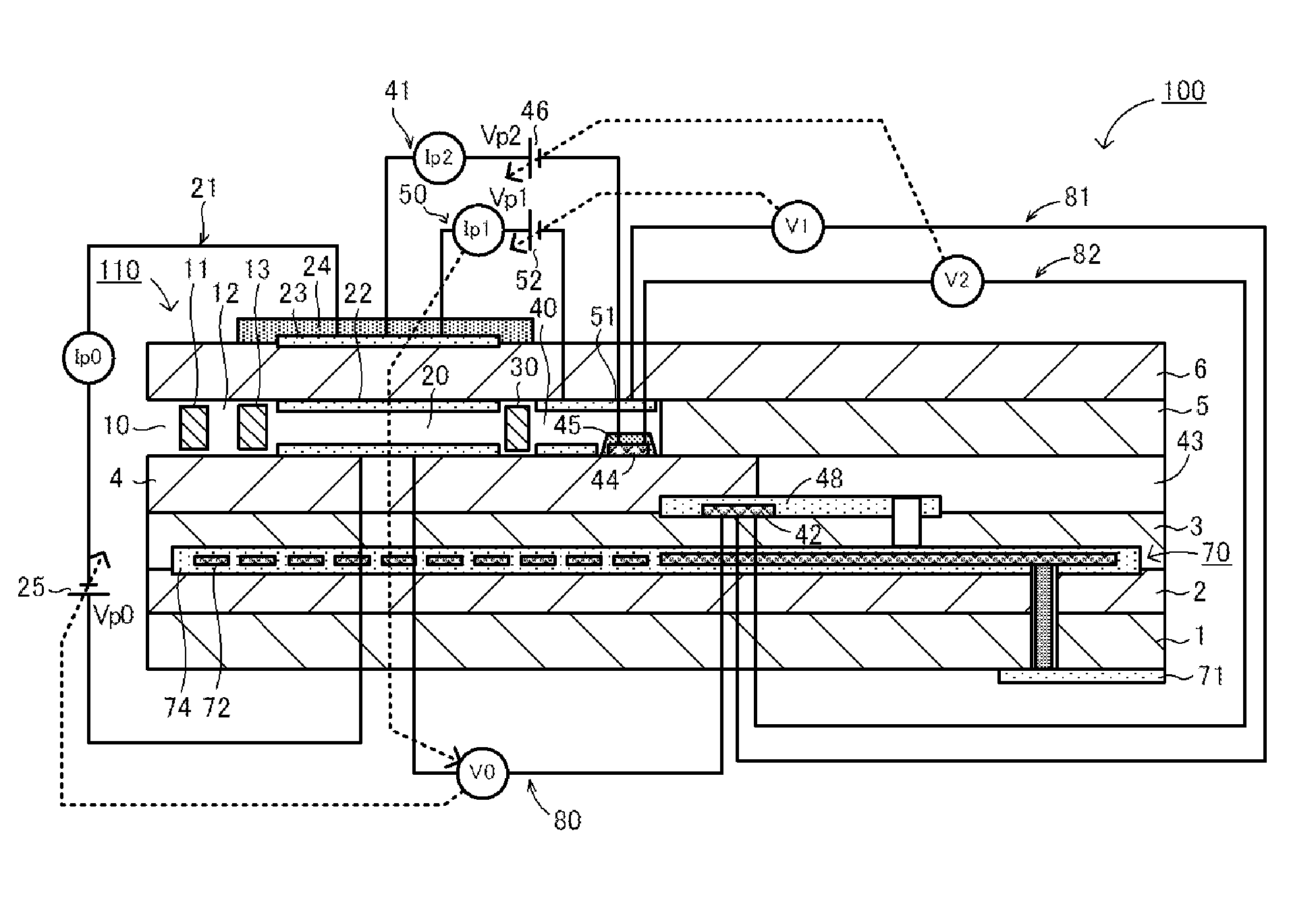
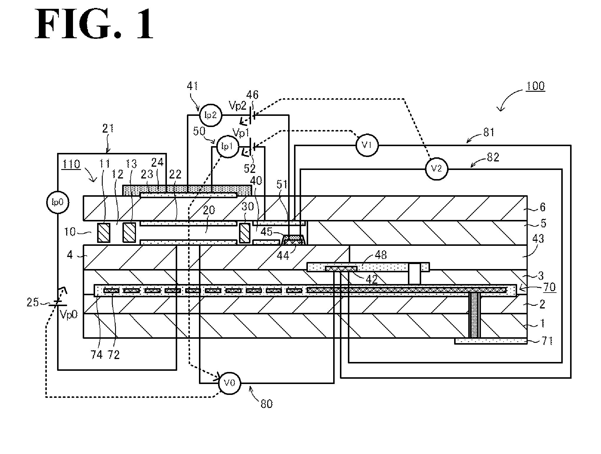
[0066]The NOx sensors 100 of Examples 1 to 9 were manufactured according to the following basic procedures. First, six green sheets were fabricated by shaping a zirconia powder, added with 4 mol % of yttria as a stabilizer, into the form of a tape. Then, patterns for the electrodes, the insulation layers, the resistance heating elements, etc. were formed by screen printing on the six green sheets corresponding respectively to the first substrate layer 1, the second substrate layer 2, the third substrate layer 3, the first solid electrolyte layer 4, the spacer layer 5, and the second solid electrolyte layer 6 of the NOx sensor 100. Thereafter, those sheets were stacked and integrated to form a laminate. The laminate was cut into pieces each corresponding to the size of one NOx sensor 100. A portion of the upper surface of each of the cut laminates, the portion operating as the outer pump electrode 23, was exposed to the outside. The predetermined slurry was screen-printed to cover th...

examples 13 to 17

[0072]In the Examples 13 to 17, before firing the laminate, the characteristic stabilizing layers 24 were each formed by the screen printing method in accordance with the above-described basic procedures such that the thickness of the characteristic stabilizing layer 24 has an average value of 50 μm. On that occasion, the number of repeated printings, the viscosity of the slurry, etc. were adjusted as appropriate to form the characteristic stabilizing layers 24 with thickness variations of 5%, 10% and 20%. On the laminate after the firing, it was likewise tried to form the characteristic stabilizing layers with thickness variations of 5%, 10% and 20%. However, the thickness variation of less than 30% was not obtained. In other words, only the characteristic stabilizing layers with thickness variations of 30% or more were obtained even when the number of repeated printings, the viscosity of the slurry, etc. were adjusted. The reason presumably resides in that the printed surface is n...


PUM

PropertyMeasurementUnit
thicknessaaaaaaaaaa
thicknessaaaaaaaaaa
porosityaaaaaaaaaa

Abstract

A NOx sensor 100 includes a sensor device 110 and a heater 70 capable of heating the sensor device 110. The sensor device 110 includes an inner pump electrode 22 and an outer pump electrode 23 disposed respectively on the inner side and the outer side of a solid electrolyte layer 6. The sensor device 110 detects the concentration of NOx by introducing a gas to be measured into a first inner vacancy 20, pumping out oxygen in the gas to be measured from the inner pump electrode 22 to the outer pump electrode 23, introducing the gas to be measured, from which the oxygen has been pumped out, into a second inner vacancy 40, reducing the NOx in the gas to be measured, to thereby generate oxygen, and detecting the generated oxygen. A characteristic stabilizing layer 24 covers the outer pump electrode 23 and is made of a porous body with a thickness of 10 to 200 μm and a thickness variation of 20% or less.

Description

BACKGROUND OF THE INVENTION[0001]1. Field of the Invention[0002]The present invention relates to a gas sensor and a method for manufacturing the gas sensor.[0003]2. Description of the Related Art[0004]Hitherto, a NOx sensor has been known as a thick-film multilayer gas sensor of the limiting current type. The NOx sensor includes a sensor device (element) for detecting the concentration of NOx in a gas to be measured (i.e., a gas under measurement), and a heater disposed adjacent to the sensor device. The sensor device includes an inner pump electrode and an outer pump electrode disposed on the inner side and the outer side of a base member, respectively, which is made of a solid electrolyte layer having oxygen-ion conductivity. The inner pump electrode introduces the gas under the measurement into a first chamber that is exposed to the outside, and then pumps out oxygen in the gas under the measurement from the inner pump electrode to the outer pump electrode. The gas under the meas...

Claims


Application Information

Patent Timeline
Patent Type & Authority Applications(United States)
IPC IPC(8): G01N27/30C03B29/00
CPCG01N27/4075G01N33/0037G01N27/4077Y02A50/20
Inventor HORISAKA, SUMIKOFUJITA, HIROKIMURAKAMI, MIKAITO, TAKASHI
Owner NGK INSULATORS LTD
Why Eureka
Try Eureka