
Moving structure and light scanning mirror using the same

Inactive Publication Date: 2011-08-04
PANASONIC CORP
View PDF18 Cites 32 Cited by
  • Summary
  • Abstract
  • Description
  • Claims
  • Application Information

AI Technical Summary

Benefits of technology

[0025]According to the invention of claim 1, since the stoppers restrain the displacement of the moving plate by contacting a part of the moving structure, the hinges and the comb tooth electrodes become hard to be broken even when a mechanical shock is applied to them from outside. Thereby, it is possible to enhance crashworthy of the moving structure.
[0026]According to the invention of claim 2, even when the moving plate displaces in the in-plane direction by acting on the mechanical shock from outside, a quantity of the displacement of the moving plate in the in-plane direction is restrained by the stoppers. Therefore, since the moving plate may not displace largely, and thus, breakages of the hinges can be prevented, it is possible to enhance crashworthy of the moving structure.
[0027]According to the invention of claim 3, since the stoppers are disposed in the vicinities of the hinges, it is possible to restrain the displacement of the moving plate in the in-plain direction effectively, even when the moving plate is inclined with respect to the frame. In addition, since level of precision required to locations and shapes of the stoppers is lower in comparison with the conventional case of forming a pivot shaped protrusion, the moving structure can be manufactured relatively easier. Moreover, since the stoppers may not contact the hinges, it is possible to prevent the breakage of the hinges surely.
[0028]According to the invention of claim 4, since the comb tooth of the comb tooth electrodes may not contact the moving plate, the frame or the like, it is possible to prevent the breakage of the comb tooth electrodes and to enhance the crashworthy of the moving structure.
[0029]According to the invention of claim 5, since the stoppers can be formed easily by processing a member which constitutes the moving plate or the frame when forming the moving plate or the frame, the moving structure can be manufactured much easier.
[0030]According to the invention of claim 6, the quantity of the displacement of the moving plate can be restrained by contacting the stopper with a side of the recess in the displacement of the moving plate. Therefore, it is possible to configure a structure to restrain the quantity of the displacement of the moving plate much easier and stronger.

Problems solved by technology

However, when thinning the hinges, the hinges become weak for a physical shock, and the hinges may be broken when a mechanical shock is applied from outside, and thus, the light scanning mirror may become immovable.
However, even though the cover substrate is provided, displacement of the moving plate is not restrained in such a structure, when a mechanical shock is applied from outside, the hinges may be broken before the moving plate contacts the cover substrate.
However, there is a problem that the micro-mirror device is not easily manufactured because the pivot is necessary to be formed precisely at a predetermined position to correspond to the central portion of the moving plate and proximate to the moving plate.
Since each comb teeth is thin and weak, it may be broken due to it contacts the stationary frame or the moving plate.

Method used


Image

  • Moving structure and light scanning mirror using the same
  • Moving structure and light scanning mirror using the same
  • Moving structure and light scanning mirror using the same

Examples


first embodiment

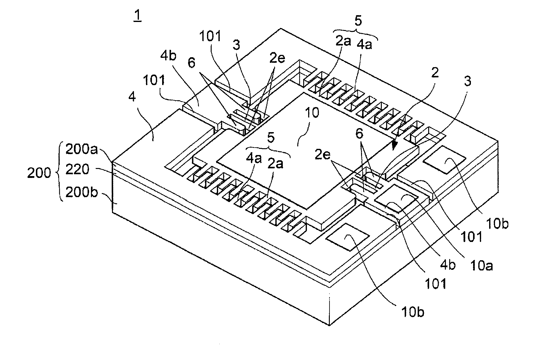
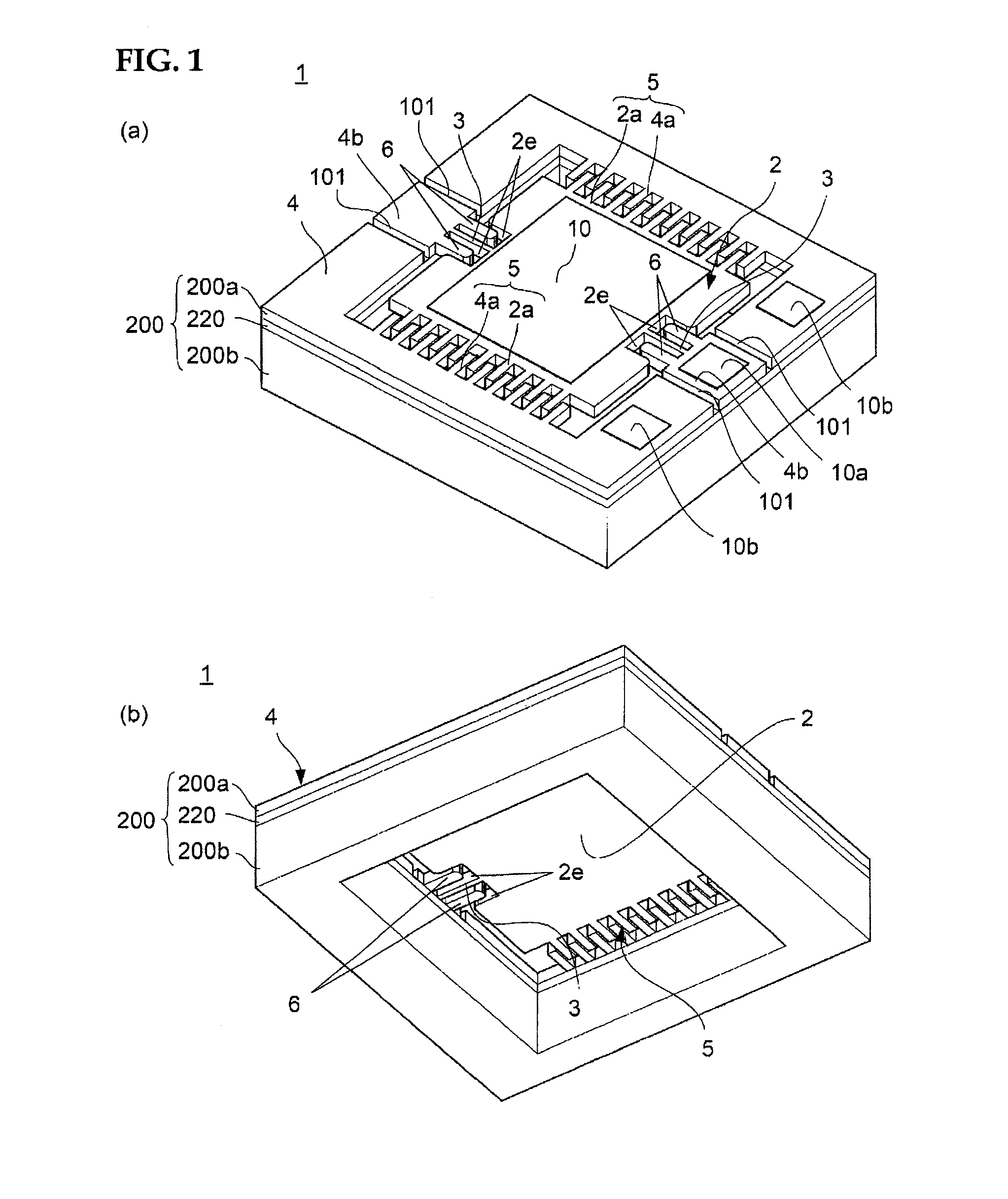
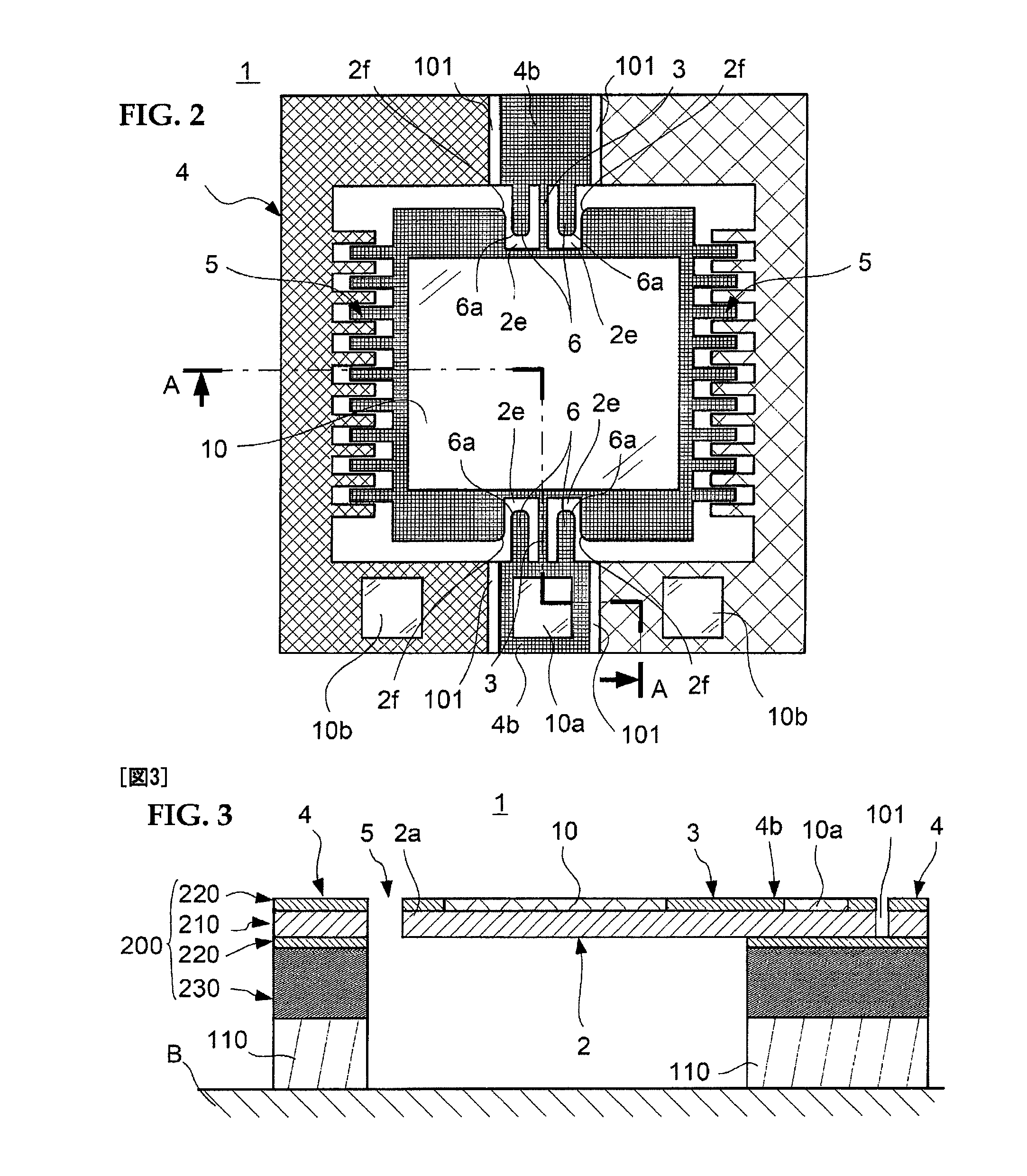
[0064]A first embodiment of the present invention is described below with reference to figures. FIGS. 1(a) and (b), FIG. 2 and FIG. 3 show an example of a light scanning mirror (a moving structure) in accordance with this embodiment. The light scanning mirror 1 is a miniature one which is to be mounted on an optical instrument such as a bar-code reader, a projector apparatus which projects an image on an external screen, or a light switch, and has a function to scan light beams which are incident from external light source or the like (not shown in the figures).

[0065]First, a configuration of the light scanning mirror 1 is described. The light scanning mirror 1 is a MEMS (Micro Electro Mechanical System) device manufactured by processing a SOI (Silicon on Insulator) substrate 200 using so-called micro machining technology. The SOI substrate 200 is a triple-layered substrate consisting of a first silicon layer (activation layer) 200a and a second silicon layer (substrate layer) 200b ...

second embodiment

[0081]Subsequently, a second embodiment of the present invention is described. FIG. 5 shows a light scanning mirror 21 in accordance with the second embodiment. Hereinafter, elements similar to those in the above mentioned first embodiment are designated by the same reference marks, and only the portions different from the above first embodiment are described. The light scanning mirror 21 has a moving plate 22 of a different shape from the moving plate 2 of the light scanning mirror 1. In other words, as shown in the figure, the moving plate 22 has no recess 2e but has contacting protrusions 22e formed to protrude toward the stationary frame 4 respectively at positions distant much farther from the hinges 3 than the stoppers 6 at both side portions of the hinges 3. Other configurations of the moving plate 22 and a configuration of the light scanning mirror 21 other than the moving plate 22 are similar to those of the light scanning mirror 1 in the first embodiment. This light scanni...

third embodiment

[0083]FIG. 7 shows a light scanning mirror 41 in accordance with a third embodiment of the present invention. The light scanning mirror 41 comprises a moving plate 42 having stoppers 46 formed along the hinges 3 replacing with the moving plate 2 of the light scanning mirror 1. In addition, contacting protrusions 44e are formed at the supporting portions 4b of the stationary frame 4. The contacting protrusions 44e are respectively formed to protrude toward the moving plate 42 at positions at both sides of the hinges 3 and distant farther from the hinges 3 than the stoppers 46. The configurations of the light scanning mirror 42 other than the moving plate 42 and the contacting protrusions 44e are similar to those of the light scanning mirror 1 in the first embodiment. This light scanning mirror 41 can be manufactured easily by forming the shapes including the moving plate 42 and the contacting protrusions 44e on the first silicon layer 200a by processing the bulk micro machining techn...


PUM


Abstract

In a semiconductor mechanical structure, hinges may not be broken even when a mechanical shock is applied from outside, and thus, crashworthy is enhanced. A light scanning mirror includes a moving plate, a twin hinges constituting an axis of swing motion of the moving plate wherein an end of each hinge is connected to both ends of the moving plate, a stationary frame which is disposed to surround peripheries of the moving plate and supports another end of each of the twin hinges, and stoppers formed on the stationary frame. When the moving plate displaces in a lateral direction, the stopper contacts a side end portion of a recess of the moving plate, so that the displacement of the moving plate in the lateral direction is restrained. Thereby, the breakage of the hinges is prevented even when the mechanical shock is applied from outside.

Description

TECHNICAL FIELD[0001]The present invention relates to a moving structure having a moving plate which is formed on a semiconductor substrate and configured to be pivoted swingably by hinges.BACKGROUND ART[0002]Conventionally, it is known that some optical instruments such as bar-code readers or projectors use a light scanning mirror to scan light beams incident to a mirror by swinging a moving plate to which the mirror is provided (see patent document 1 to patent document 3, for example). As for the light scanning mirror, a miniature one having a semiconductor moving structure formed by using micro machining technology is known. Such a moving structure has a moving plate to which a mirror face is formed when it is used as a light scanning mirror and a stationary frame which supports the moving plate. The moving plate and the stationary frame are coupled by hinges each other. The moving plate is driven by a pair of comb tooth electrodes facing each other and formed between the moving ...

Claims


Application Information

Patent Timeline
IPC IPC(8): G02B26/10H02N1/00F16C11/04
CPCB81B3/0051B81B2201/042B81C2201/112Y10T403/32557B81C2203/031G02B26/0841H02N1/006B81C2203/0118
Inventor TACHIBANA, HIROAKINOGE, HIROSHIKAWANO, KIYOHIKOUEDA, HIDEKI
Owner PANASONIC CORP
Learn More