Multi-site cranial stimulation method and system

a cranial stimulation and multi-site technology, applied in the field of multi-site cranial stimulation methods, to achieve the effect of improving the results obtained

Active Publication Date: 2011-08-04
STARLAB BARCELONA SL
View PDF9 Cites 37 Cited by
  • Summary
  • Abstract
  • Description
  • Claims
  • Application Information

AI Technical Summary

Benefits of technology

[0024]One of the purposes of the mentioned monitoring is to provide one or more signals obtained as a result of the monitoring, or monitored signals, to control said stimulation by means of varying said stimulus signals depending on the monitored signals, applying the proposed method. In this manner, the stimulation is adapted or self-calibrated in real time to the changes observed in the brain activity, which is truly advantageous for preventing, up to a certain point, the possible problems and inaccuracies associated with the less reliable positioning of the stimulation elements or with the unknown geometry of the patient's or user's head which, as will be explained below, negatively affect the final distribution of the electric (or magnetic) field on the brain.
[0042]The method comprises associating a marking signal to each of the stimulus signals, for example by means of superpositioning the same on the corresponding stimulus signal in each stimulation element, in order to improve the location of each signal induced by the application of a corresponding stimulus signal and to improve said distinction between the electric signals induced by the stimuli and the signals indicative of brain activity, be it natural activity or the result of the applied stimuli, upon analyzing the monitored signals.
[0044]The process for recovering the signal dispersion in each tomography voxel allows recovering the contribution made by each stimulation element in each voxel (using the superposition principle) and it is used, applying the method proposed by the first aspect of the invention, to improve the guiding by means of adjusting the intensities of the stimulus signals applied in the different stimulation elements.
[0071]Although there are earlier works on some of said applications as indicated, the application of the method and the system proposed by the present invention seek to greatly improve the results obtained, as well as the functionality and freedom for adjustment and adaptation of the different parameters inherent to the stimulation systems compared to conventional proposals.

Problems solved by technology

A truly important challenge in neuroscience is mapping and analyzing spatiotemporal patterns of the activity of large populations of neurons which are believed to be responsible for processing information in the human brain.

Method used


Image

  • Multi-site cranial stimulation method and system
  • Multi-site cranial stimulation method and system

Examples


Embodiment Construction

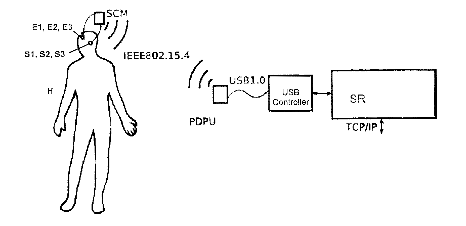
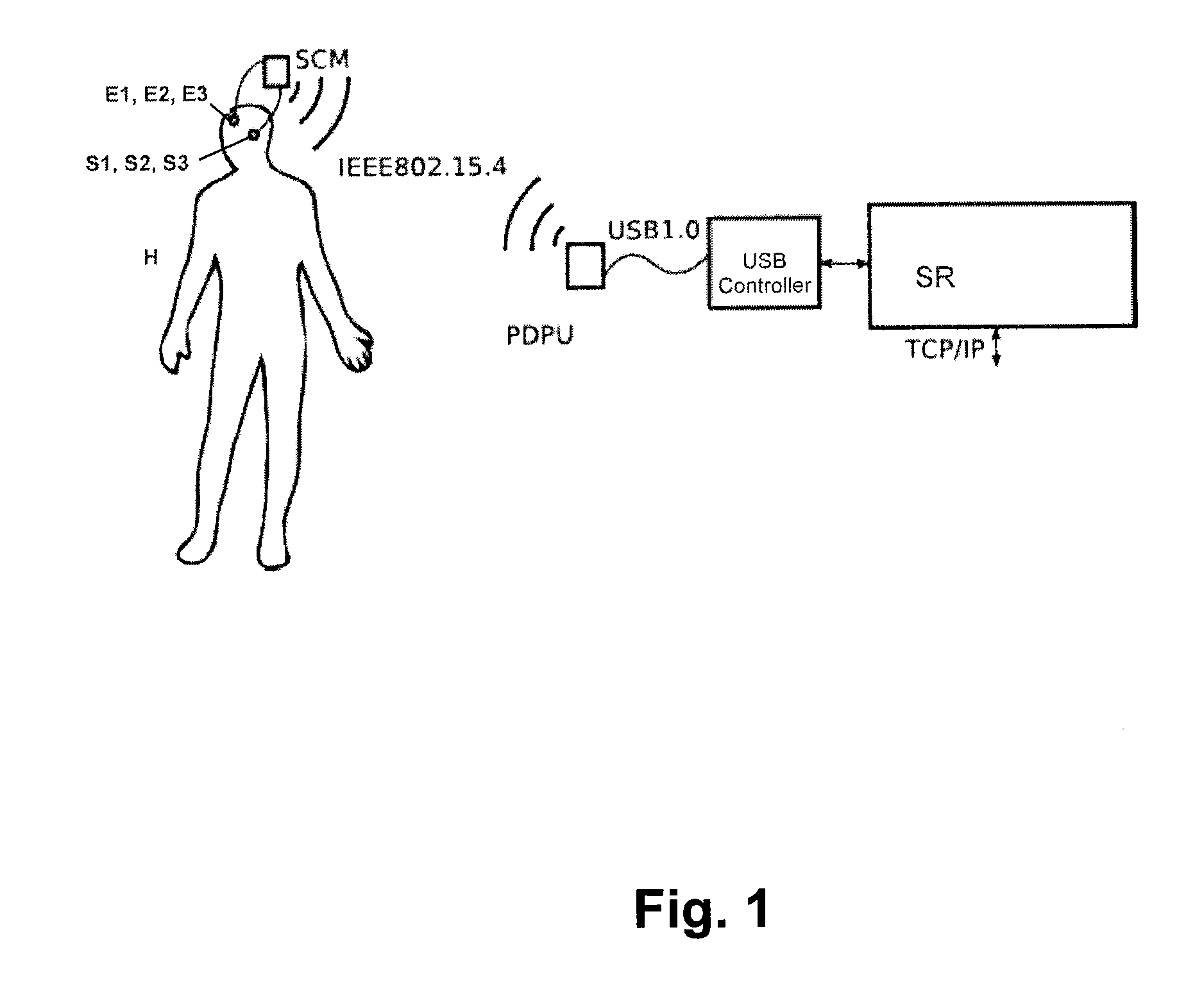
[0074]FIG. 1 illustrates the system proposed by the second aspect of the invention for an embodiment in which a patient H is provided with the aforementioned plurality of stimulation elements E1, E2 . . . En (schematically depicted by a small circle which represents an ordered assembly or array of electrodes) adjacent to a corresponding plurality of different regions of the brain.

[0075]As described above, the system proposed by the second aspect of the invention also comprises a series of electrophysiological sensors S1, S2 . . . Sn arranged adjacent to specific regions of the brain and in connection with said processing unit of said electronic system to monitor the brain activity of said brain. Said electrophysiological sensors S1, S2 . . . Sn are also illustrated in FIG. 1 adjacent to the brain of patient H (they are also schematically depicted by a small circle which represents an ordered assembly or array of sensors).

[0076]The proposed system comprises an electronic system in co...


PUM


Abstract

The method includes applying individual stimuli to different regions of a brain the application of specific stimulus signals to corresponding stimulation elements arranged adjacent to the regions of the brain. The method includes constructing one or more simplified models of the brain, or of one or more sectors of the brain, considering the brain or the sector thereof, as appropriate, as a non-linear coupled oscillating system, and includes determining the stimulus signals so that the latter are suitable for exciting one or more natural vibration modes of the non-linear coupled oscillating system. The system includes stimulation elements (E1, E2 . . . En) arranged adjacent to regions of a brain, and an electronic system in connection with the stimulation elements (E1, E2 . . . En) and intended for applying thereto corresponding stimulus signals and for determining same by applying the proposed method.

Description

FIELD OF THE ART[0001]The present invention generally relates to a multi-site cranial stimulation method which comprises applying individual stimuli to different regions of a brain, and particularly to a method which comprises determining the stimulus signals to be applied so that they are suitable for exciting one or more natural vibration modes of the brain, or of a sector thereof seen as a non-linear coupled oscillating system.[0002]The invention also relates to a multi-site cranial stimulation system suitable for implementing the method proposed by the first aspect.PRIOR ART[0003]Various proposals focusing on both intracranial and transcranial type cranial stimulation either by means of the application of magnetic impulses in the proximity of the regions to be stimulated, or TMS stimulation, or by means of the application of electric signals, including tDCS, ENS or TES stimulation, are known. Some of them use the “multi-site” concept, i.e., the arrangement of a plurality of stim...

Claims


Application Information

Patent Timeline
Patent Type & Authority Applications(United States)
IPC IPC(8): A61N1/05A61N2/00
CPCA61N1/0529A61N1/0531A61N1/36014A61N1/36017A61N1/36025A61N1/37252A61M2230/10A61M21/00A61M2021/0055A61M2021/0072A61M2205/3569A61M2205/3592A61M2205/8206A61B5/0476A61B5/369A61N1/00A61N2/00
Inventor RUFFINI, GIULIOFARRES, ESTEVEGRAU, CARLES
Owner STARLAB BARCELONA SL
Why Eureka
Try Eureka