Robotic high density welding body shop

a welding body shop and robot technology, applied in the field of motor vehicle manufacturing, can solve the problems of large factory footprint, large manpower requirements of typical motor body shops, complex equipment and procedures, etc., and achieve the effects of optimizing material delivery, facilitating batch build, and unfavorable production

Active Publication Date: 2011-08-11
COMAU LLC
View PDF32 Cites 8 Cited by
  • Summary
  • Abstract
  • Description
  • Claims
  • Application Information

AI Technical Summary

Benefits of technology

[0004]The invention provides a body shop configuration that provides unlimited flexibility with respect to manufacture of differing body styles; facilitates batch build with limited random potential; provides unmatched modularity with respect to tooling layout material aisles etc; provides optimum material management with respect to flexible delivery and staging and sequencing; optimizes material delivery; optimizes material loading; optimizes fixture exchange, fixture maintenance and fixture staging; maximizes robot density; facilitates an optimum maintenance strategy; facilitates production scheduling and floor space utilization; desensitizes product architecture; desensitizes build sequence; optimizes manpower utilization, traffic engineering, and equipment utilization; and facilitates engineering build, installation, maintenance, and material management.

Problems solved by technology

Whereas a myriad of vehicle body shop configurations have been proposed or implemented, the typical motor body shop continues to require large amounts of manpower, continues to consume a large factory footprint, continues to require complex equipment and procedures to supply component parts to the assembly line, and continues to require complex equipment and procedures to exchange tooling to facilitate model changeover.

Method used


Image

  • Robotic high density welding body shop
  • Robotic high density welding body shop
  • Robotic high density welding body shop

Examples


Embodiment Construction

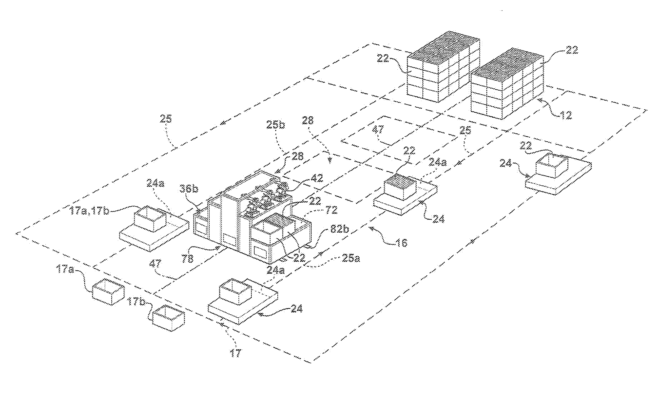
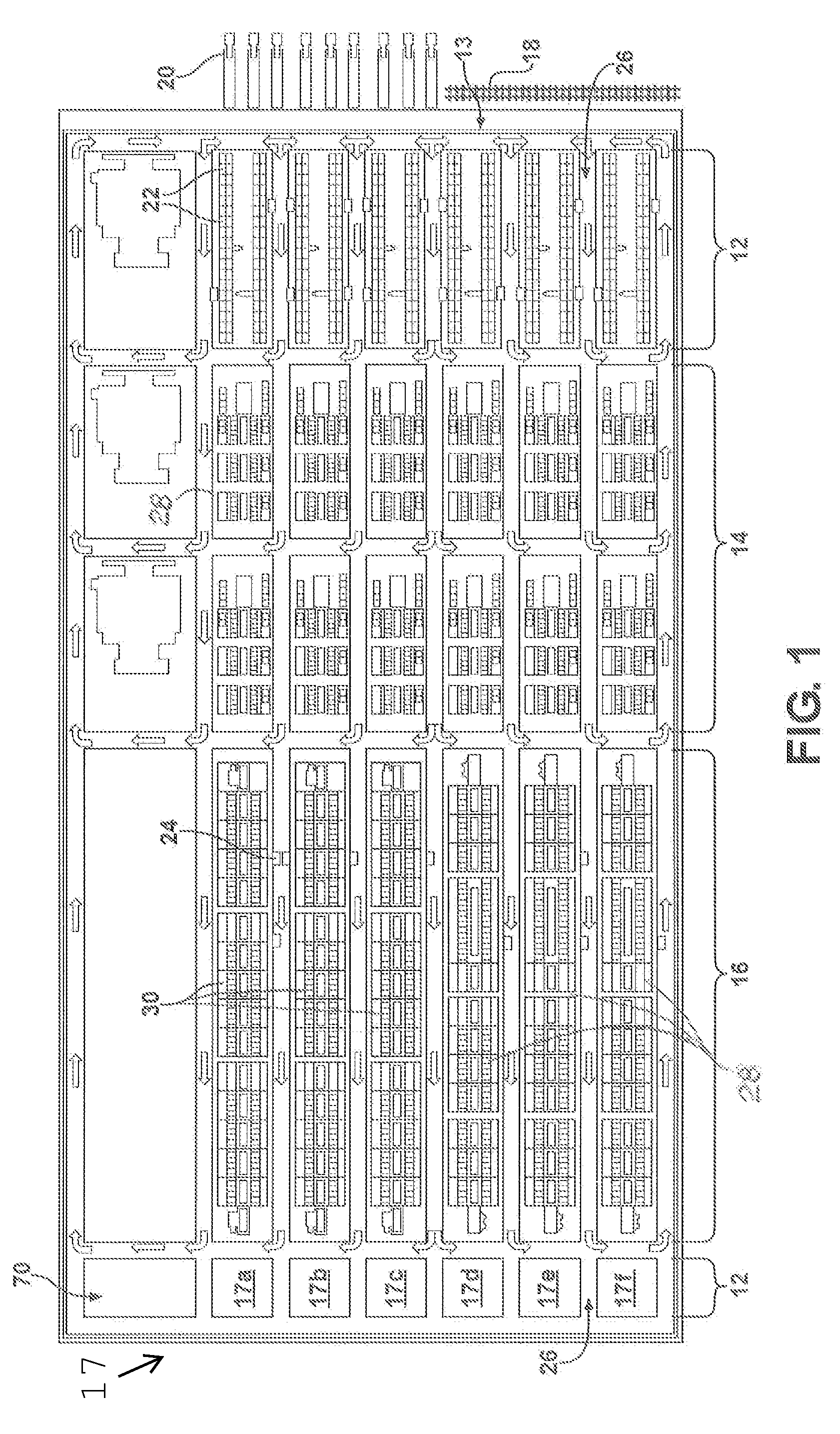
[0026]The invention body shop 10 as seen in overview in FIG. 1 includes a material management area 12, a sub-assembly area 14, a main line area 16 and a tool management area 17. Material and work flow in FIG. 1 is essentially from right to left with provision for return movement and tooling exchange flow in FIG. 1 is essentially from left to right with provision for return movement. Material management area 12 will be seen to constitute a source of component parts for the welding operations.

[0027]In material management area 12, material arriving at loading dock 13 by rail 18 or semitrailers 20 is unloaded and stacked in dunnage containers whereafter it is removed from the dunnage containers, placed in parts racks 22, and, as needed, loaded onto Automatic Guided Vehicles (AGV) 24 for automatic battery powered movement down aisles 26 to selectively deliver the materials to sub assembly area 14 and main line area 16.

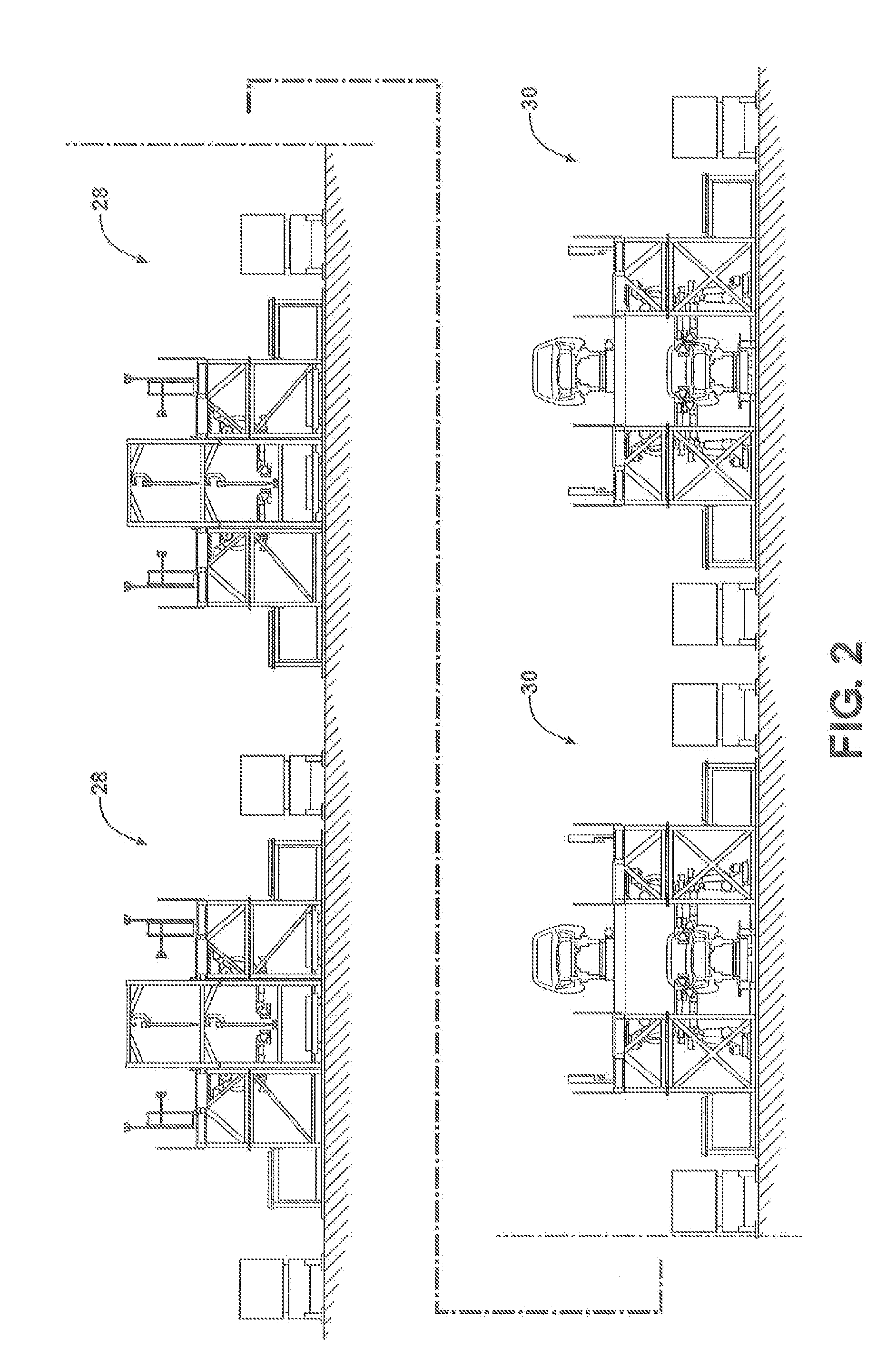
[0028]Sub assembly area 14 consists of six parallel rows of roller ass...


PUM

PropertyMeasurementUnit
areasaaaaaaaaaa
areaaaaaaaaaaa
movementaaaaaaaaaa

Abstract

A method and apparatus for managing the delivery of component parts and tooling to a robotic welding assembly positioned on a motor vehicle body assembly line. Automatic guided vehicles deliver component parts from a source of parts to a parts staging area on the robotic welding assembly including a substage awaiting area, a substage in-use area and a substage empty area, and further automatic guided vehicles deliver tooling from a tooling management area to the robotic welding assembly whereafter the tooling, upon model changeover, is moved to a tooling use area proximate the assembly line whereafter, upon further model changeover, the tooling is removed from the tooling use area and loaded onto an automatic guided vehicle for return to the tooling management area.

Description

CROSS-REFERENCE TO RELATED APPLICATIONS[0001]This is a divisional application which claims priority benefit to U.S. patent application Ser. No. 12 / 262,722 filed on Oct. 31, 2008 and U.S. Provisional Patent Application 61 / 035,922 filed Mar. 12, 2008, the entire contents of both prior applications are incorporated herein by reference.BACKGROUND OF THE INVENTION[0002]This invention relates to motor vehicle manufacturing and more particularly to a high density welding body shop to facilitate manufacture of motor vehicle bodies.[0003]Whereas a myriad of vehicle body shop configurations have been proposed or implemented, the typical motor body shop continues to require large amounts of manpower, continues to consume a large factory footprint, continues to require complex equipment and procedures to supply component parts to the assembly line, and continues to require complex equipment and procedures to exchange tooling to facilitate model changeover.SUMMARY OF THE INVENTION[0004]The inven...

Claims


Application Information

Patent Timeline
Patent Type & Authority Applications(United States)
IPC IPC(8): B23Q7/14B23P17/00B23P21/00
CPCY10T29/53539B23K37/047Y10T29/53B62D65/02B23P2700/50Y10T29/53417B62D65/00Y10T29/49829Y10T29/53313B23P21/004Y10T29/53548Y10T29/53383
Inventor KILIBARDA, VELIBOR
Owner COMAU LLC
Why Eureka
Try Eureka