Control device of internal combustion engine

a control device and internal combustion engine technology, applied in the direction of electric control, machines/engines, output power, etc., can solve the problems of large amount of combustion gas remaining in the combustion chamber, insufficient conversion of combustion gas energy to kinetic energy of the piston, and advance of the opening timing, so as to prevent the occurrence of torque fluctuation

Inactive Publication Date: 2011-08-11
TOYOTA JIDOSHA KK
View PDF2 Cites 11 Cited by
  • Summary
  • Abstract
  • Description
  • Claims
  • Application Information

AI Technical Summary

Benefits of technology

[0010]According to the present aspect, if the output torque of the internal combustion engine is predicted as becoming too small, execution of the early exhaust valve closing control is prohibited. Due to this, at the time of a deceleration operation of the internal combustion engine, by performing early exhaust valve closing control when the output torque of the internal combustion engine is sufficient, it is possible to make the state of combustion of the internal combustion engine a good state, while by prohibiting early exhaust valve closing control when the output torque of the internal combustion engine is not sufficient, it is possible to prevent the occurrence of a torque fluctuation which would invite deterioration of drivability and engine stalling.
[0013]According to the present aspect, if the output torque of the internal combustion engine is predicted as becoming too small, the ignition timing is advanced. Due to this, at the time of a deceleration operation of the internal combustion engine, by performing the early exhaust valve closing control when the output torque of the internal combustion engine is sufficient, it is possible to make the state of combustion of the internal combustion engine a good state, while by making the ignition timing advance when the output torque of the internal combustion engine is not sufficient, it is possible to prevent the occurrence of a torque fluctuation which would invite deterioration of drivability and engine stalling.
[0014]In a third aspect of the present invention, there is provided a control device of an internal combustion engine provided with a fuel injector which injects fuel to the inside of an intake port and an exhaust variable valve timing mechanism able to change a valve timing of an exhaust valve, the control device executing early exhaust valve closing control which advances a closing timing of the exhaust valve when a condition for executing early exhaust valve closing control stands, wherein, at the time of a deceleration operation of the internal combustion engine, even when the condition for executing early exhaust valve closing control stands, execution of the early exhaust valve closing control is prohibited when the engine speed is predicted as becoming lower than a limit speed.
[0015]Note that, “limit speed” means the lowest engine speed necessary for maintaining the operation of the internal combustion engine or the lowest engine speed necessary for preventing rapid torque fluctuation compared with the engine speed of several cycles before the current cycle.
[0016]In a fourth aspect of the present invention, there is provided a control device of an internal combustion engine provided with a fuel injector which injects fuel to the inside of an intake port and an exhaust variable valve timing mechanism able to change a valve timing of an exhaust valve, the control device executing early exhaust valve closing control which advances a closing timing of the exhaust valve when a condition for executing early exhaust valve closing control stands, wherein, at the time of a deceleration operation of the internal combustion engine, even when the condition for executing early exhaust valve closing control stands, the ignition timing is advanced when the engine speed is predicted as becoming lower than a limit speed.

Problems solved by technology

Due to this, even after the exhaust valve closing, a large amount of combustion gas remains in the combustion chamber.
That is, when it is not possible to change the operating angle of the exhaust valve, advance of the closing timing of the exhaust valve leads to advance of the opening timing of the exhaust valve.
As a result, the energy of the combustion gas can no longer be sufficiently converted to kinetic energy of the piston and a drop in the output torque from the internal combustion engine is invited.
Torque shock occurs due to the rapid drop of the output torque or the output torque falls too much and engine stalling is invited in some cases.

Method used


Image

  • Control device of internal combustion engine
  • Control device of internal combustion engine
  • Control device of internal combustion engine

Examples


Embodiment Construction

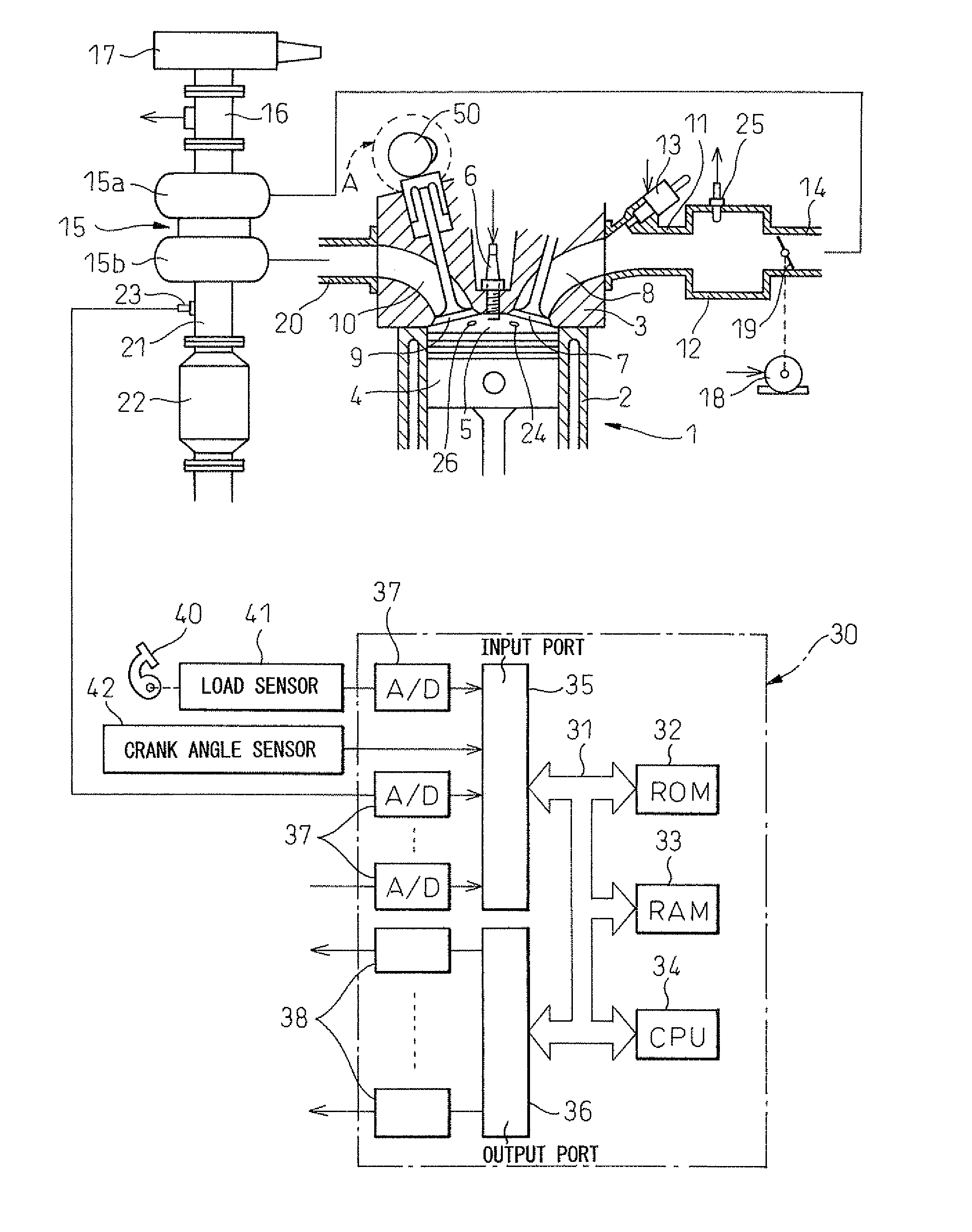
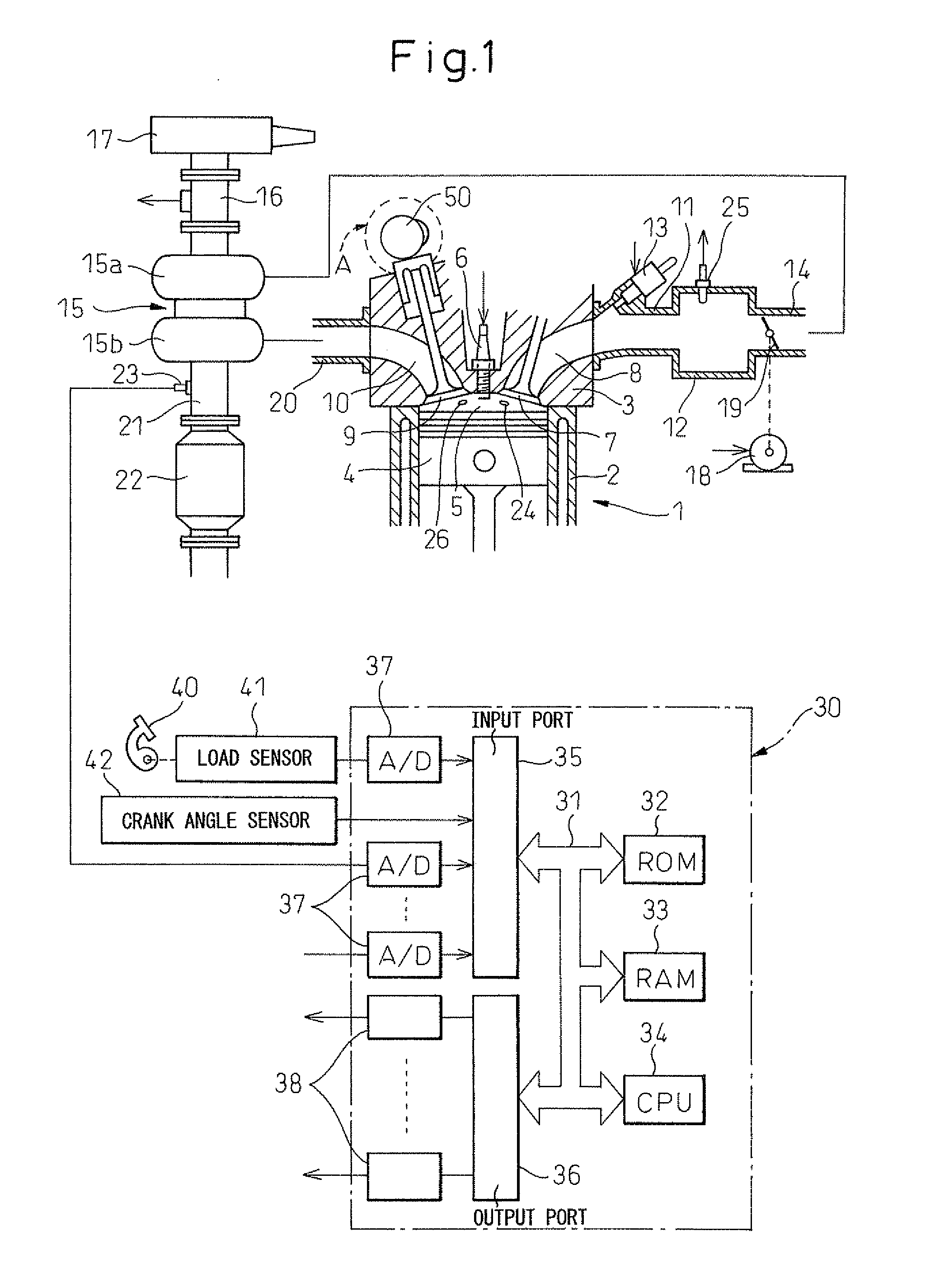
[0030]Below, an embodiment of the present invention will be explained in detail with reference to the drawings. Note that, in the drawings, the same or similar elements are assigned the common reference numerals. FIG. 1 is an overall view showing the internal combustion engine in which the control device of the present invention is used.

[0031]Referring to FIG. 1, an engine body 1 is provided with a cylinder block 2, cylinder head 3, pistons 4, combustion chambers 5, and spark plugs 6 arranged at the centers of the tops of the combustion chambers 5, intake valves 7, intake ports 8, exhaust valves 9, and exhaust ports 10. Each intake port 8 is connected through an intake branch pipe 11 to a surge tank 12. Each intake branch pipe 11 is provided with fuel injector 13 to inject fuel toward the inside of the corresponding intake port 8. Each exhaust valve 9 is provided with an exhaust variable valve timing mechanism A able to control a phase angle of the exhaust valve 9 (that is, valve ti...


PUM


Abstract

An internal combustion engine is provided with a fuel injector which injects fuel into an intake port and exhaust variable valve timing mechanism which changes a valve timing of an exhaust valve. A control device executes early exhaust valve closing control which advances a closing timing of an exhaust valve when conditions for executing early exhaust valve closing control stand. The control device includes a torque detecting means which detects an output torque output by an engine body. At the time of deceleration of the engine, even when the condition for executing early exhaust valve closing control stands, execution of early exhaust valve closing control is prohibited when it is predicted that the output torque will become smaller than the limit torque. Thus, due to execution of the early exhaust valve closing control, a large torque fluctuation is prevented from occurring at the time of deceleration of the engine.

Description

TECHNICAL FIELD[0001]The present invention relates to a control device of an internal combustion engine.BACKGROUND ART[0002]In the past, an internal combustion engine which has an exhaust variable valve timing mechanism which can change the phase angle (valve timing) of an exhaust valve has been known. In this internal combustion engine, for example, at the time of cold start of the internal combustion engine, control is performed for advancing the closing timing of the exhaust valve with respect to intake top dead center for the purpose of decreasing the emission of unburned hydrocarbons (unburned HC) from the engine body (for example, Japanese Patent Publication (A) No. 2003-120348).[0003]That is, at the time of engine startup, not all of the fuel which is injected from a fuel injector is burned. Part of the fuel remains as unburned HC in the combustion gas. Here, in the system described in Japanese Patent Publication (A) No. 2003-120348, when in a state where combustion gas canno...

Claims


Application Information

Patent Timeline
Patent Type & Authority Applications(United States)
IPC IPC(8): F02M51/00
CPCF01L1/143F02D2041/001F01L2001/34426F02B37/00F02B2275/16F02D13/0219F02D13/0249F02D37/02F02D41/047F02D41/12F02D41/126F02D41/1497F02D2200/1002F02D2250/21Y02T10/123Y02T10/18F02D41/123F01L1/3442Y02T10/12F02D13/02F02D41/04
Inventor TOMIMATSU, MAKOTOHOSHI, KOICHISUDA, SHOGO
Owner TOYOTA JIDOSHA KK
Why Eureka
Try Eureka