Circuit Board
- Summary
- Abstract
- Description
- Claims
- Application Information
AI Technical Summary
Benefits of technology
Problems solved by technology
Method used
Image

Examples
first embodiment
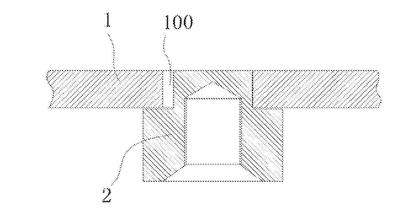
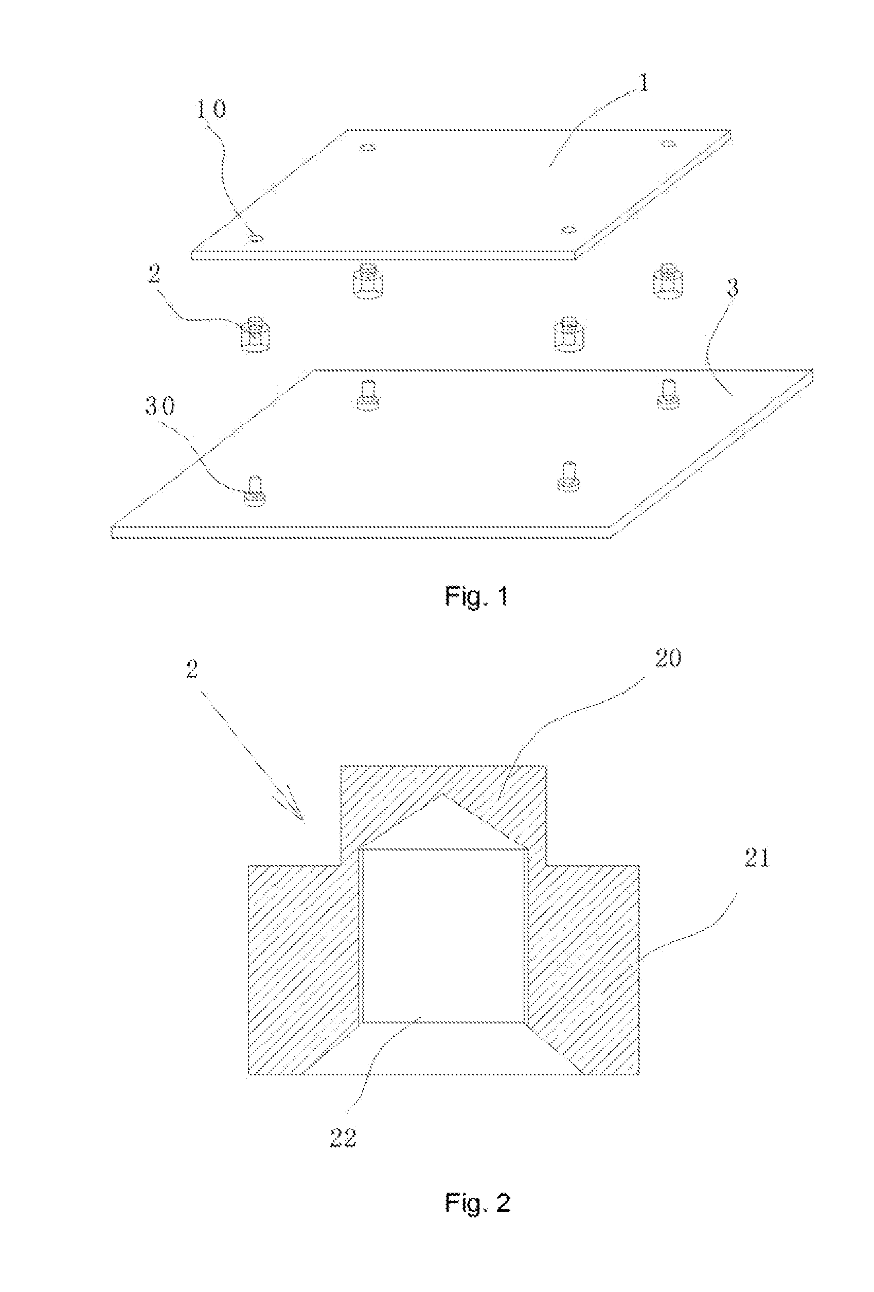
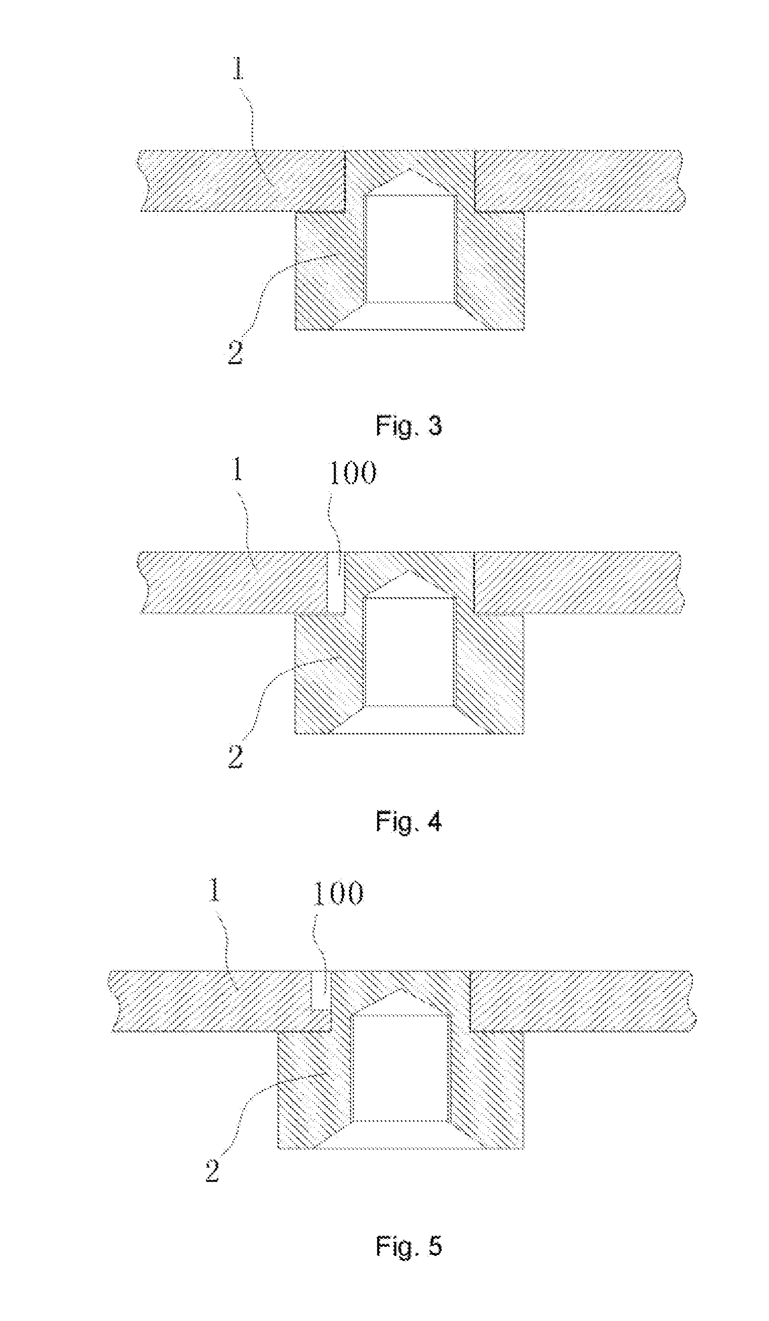
[0035]A circuit board 1 comprises at least one mounting hole 10 for coupling a weld screw 2, and at least one notch 100 for receiving solder is formed in an inner wall of the mounting hole, as shown in FIG. 4, for example. In this embodiment, a thickness of the circuit board 1 is about 2 mm As shown in FIG. 2, the weld screw 2 is a T-shaped screw, which comprises a welded part 20, a connected part 21, and a threaded hole 22. The welded part 20 is welded in the mounting hole 10, and the threaded hole 22 is screwed to the screw 30. In this embodiment, the welded part 20 has a diameter of about 4 mm and a height of about 2 mm. The connected part 21 has a diameter of about 6 mm and a height of about 3.3 mm. It should be noted that the T-shaped screw and the configuration or shape of the mounting hole are only for illustrative purpose rather than limitation.
[0036]The threaded hole 22 is a blind hole or a counter sink, so that solder can be applied over the welded part 20 for welding. In ...
second embodiment
[0044]The present embodiment is similar to the first embodiment. Therefore, the same or similar detailed description thereof is hereby omitted for clarity purpose.
[0045]The present embodiment provides another type of notch. As shown in FIGS. 4 and 7, the cylindrical mounting hole 10 has a notch 100 formed on its wall, and the notch 100 is a via-hole notch extending from the upper surface of circuit board 1 to the lower surface of circuit board 1. The via-hole notch may be a rectangular one, which can be easily formed by punching.
third embodiment
[0046]The present embodiment is similar to the first embodiment. Therefore, the same or similar detailed description thereof is hereby omitted for clarity purpose. In the present embodiment, another type of notch is provided. As shown in FIGS. 5 and 12, the notch 100 does not run through the whole circuit board, but is formed as steps or a counter sink from the upper surface of the circuit board 1 to the lower surface of the circuit board 1.
PUM
 Abstract
Description
Claims
Application Information
 - R&D
- Intellectual Property
- Life Sciences
- Materials
- Tech Scout
- Unparalleled Data Quality
- Higher Quality Content
- 60% Fewer Hallucinations
Browse by: Latest US Patents, China's latest patents, Technical Efficacy Thesaurus, Application Domain, Technology Topic, Popular Technical Reports.
© 2025 PatSnap. All rights reserved.Legal|Privacy policy|Modern Slavery Act Transparency Statement|Sitemap|About US| Contact US: help@patsnap.com